Wind often governs lateral design and roof uplift on steel industrial buildings, yet the ASCE 7 procedure is easy to misapply when editions mix. This post answers three common questions, then works an example for a steel-frame building. It extends our overview of structural engineering for industrial plants . Steel-frame building under construction. Photo: Dwight Burdette, CC BY 3.0, via Wikimedia Commons . What is the formula for calculating wind load? For a building, the design wind pressure on a surface is p = q G Cp − qi (GCpi), and the force is F = p × A, where A is the tributary area. The velocity pressure follows from wind velocity: qz = 0.00256 Kz Kzt Kd Ke V² in psf with V in mph, or qz = 0.613 Kz Kzt Kd Ke V² in N/m² with V in m/s. Kz is the height exposure coefficient, Kzt the topographic factor, Kd the wind directionality factor, Ke the ground elevation factor (ASCE 7-16 onward), G the gust factor (0.85 for rigid buildings) and Cp the external pressure coefficient. Th...
Get link
Facebook
X
Pinterest
Email
Other Apps
Water Hammer Calculation: Joukowsky Equation, Wave Speed and Surge Pressure Worked Example
Get link
Facebook
X
Pinterest
Email
Other Apps
-
Water hammer is the pressure surge that follows a sudden change in flow, and it is one of the few piping loads that can exceed the design pressure many times over in a fraction of a second. This post answers the five questions engineers search for most, then works through a DN300 water line with a fast and a slow valve closure and checks the result against the design pressure. It ends with the loads that matter for supports and stress analysis.
How to calculate a water hammer?
Start with the closure time. A pressure wave travels along the pipe at the wave speed a and returns from the far end after 2L/a, the critical time. If the valve closes in less than this, the closure is rapid and the full Joukowsky surge develops; if it closes more slowly, reflected waves cancel part of the rise and the peak is lower.
Joukowsky equation: ΔP = ρ a ΔV, for closure within 2L/a
Wave speed: a = √[(K/ρ) / (1 + K D / (E e))], where K is the bulk modulus of the liquid, D the inside diameter, E the pipe modulus and e the wall thickness
Critical time: tc = 2L / a
Slow closure estimate: ΔP ≈ 2 ρ L ΔV / t, for a roughly linear closure over a time t longer than 2L/a
Water has K ≈ 2.2 GPa, so a rigid pipe would give a ≈ 1,480 m/s, and pipe elasticity lowers it, to roughly 1,000 to 1,300 m/s in steel. The equations fit an Excel sheet: =SQRT((K/rho)/(1+K*D/(E*e))) gives a, and =rho*a*dV gives the surge. A single-pipe hand calculation is an upper bound; networks with pumps, vessels or several valves need a surge analysis by the method of characteristics.
What is the most common cause of water hammer?
The most common cause is a rapid change in velocity, most often a quick-closing valve: a solenoid valve, a washing machine inlet or a lever faucet in plumbing, or a motorised valve stroked too fast in process piping. Pump trips and starts, and check valves that slam shut as flow reverses, are close behind. The result is hydraulic shock: the kinetic energy of the moving column converts to pressure, which travels along the water pipe as a wave and produces the hammer effect, the bang. In steam systems a different mechanism applies. Condensate-induced hammer occurs when slugs of condensate are driven along a steam line, or when steam collapses in subcooled condensate, and it needs separate drainage and warm-up practice. A hammer analysis starts by finding which of these events is credible for the system.
How to solve a water hammer?
Solve it at the source: slow the change in velocity. Use valve actuators with a longer or two-stage closing stroke, and soft starts or variable speed drives on pumps. Replace slamming check valves with nozzle or spring-assisted types, because a check valve closes fastest when flow reverses. Reduce the design velocity, which scales the surge directly. For large lines, absorb the surge with surge tanks and air vessels, a flywheel on the pump, or a relief path. In buildings, fit a water arrestor or hammer arrestor at the quick-closing fixture, such as under the sink at a faucet. Arrestors do not fix an undersized or long line, so check the cause as well as the symptom.
A surge tank protects this penstock from water hammer pressure surges. Photo: Qurren, Wikimedia Commons, CC BY-SA 3.0.
How to determine water hammer arrestor size?
For plumbing, size by fixture units. PDI-WH 201 and ASSE 1010 define arrestor sizes A to F by the fixture units they protect, from size A for roughly 1 to 11 fixture units up to size F for the largest groups; check the current standard and the manufacturer's size chart, such as Sioux Chief's, for the exact ranges. A single washing machine supply is typically a size A arrestor installed close to the valve, in a position the manufacturer allows, with access where needed. A shock arrestor is a sealed, pre-charged piston device, so it needs no recharging. For industrial lines this method does not apply: size surge protection from the calculated surge volume and pressure, using a surge analysis, not a plumbing size chart.
Water hammer arresters fitted at washing machine supply valves. Photo: Tony Webster, Wikimedia Commons, CC BY 2.0.
What is the formula for calculating water pressure?
Static pressure follows from the liquid column: p = ρ g h, where ρ is density, g is gravity and h is the water head. A gauge reading is relative to atmosphere, and absolute pressure is pabs = patm + pgauge; one bar is about 10.2 m of water. This is how a surge is read as head: Δh = ΔP / (ρ g) = a ΔV / g. The vapour pressure of the liquid sets the floor. When a surge wave drops the absolute pressure to the vapour pressure, the water boils locally and a vapour cavity forms, called column separation, and the collapse of that cavity can create a secondary spike larger than the Joukowsky value. The same vapour pressure limit governs suction conditions, as in our NPSH available calculation post.
Worked Example: DN300 Water Line
A DN300 carbon steel line (OD 323.9 mm, Sch 40, wall 10.31 mm, inside diameter 303.3 mm) carries water at 2.0 m/s over L = 1,200 m to a shut-off valve. Take K = 2.2 GPa, ρ = 1,000 kg/m³ and E = 200 GPa. The operating pressure at the valve is 0.8 MPa and the line design pressure is 1.6 MPa (assumed). Compare a 1.5 s closure with a 20 s closure.
The rapid closure gives a peak of 3.38 MPa, more than twice the 1.6 MPa design pressure. B31.3 allows only limited occasional excursions above design pressure, for stated durations, so this exceeds them. The pipe wall itself is not the limit: Sch 40 with 12.5% mill tolerance can hold roughly 7.9 MPa by the pressure design equation (S = 138 MPa, no corrosion allowance), as in our ASME B31.3 pipe wall thickness post. The weak points are flanges, valves and supports: a Class 150 flange is rated about 1.96 MPa at ambient (assumed, Group 1.1), so Class 300 would be needed or the closure slowed. The slow closure gives 1.04 MPa and passes. The line also carries a wave force: the unbalanced load on a bend can reach ΔP × A = 2.58 × 0.0722 = 186 kN.
Practical Checks for Piping and Stress Engineers
Surge loads on supports: the wave produces a short force pulse on each bend or leg; supports and guides near elbows must resist it, as discussed in our pipe supports guide.
Unbalanced forces: calculate ΔP × A at elbows and reducers, and apply it over a duration of the leg length divided by the wave speed.
CAESAR II: model the event as a force-time history in a dynamic case, or as an equivalent static load with a dynamic load factor; the CAESAR II load-case templates post covers where such cases fit.
Pressure rating: compare peak pressure with flange, valve and fitting ratings, not only the pipe wall.
Vapour pressure: check for column separation at high points and downstream of closing valves.
Valve data: use the real closing profile, since the last part of the travel closes fastest.
Surge analysis: use specialised software for pumps, networks and long lines.
How Fluxiss Approaches Surge Loads
Fluxiss is a multidisciplinary engineering consultancy serving oil and gas, power and maritime clients. Its pipe stress team reviews surge loads alongside supports, nozzle loads and pressure design, so dynamic events are not left outside the stress report.
Frequently Asked Questions
Is the Joukowsky equation valid for slow closure?
No. It applies only when closure is faster than 2L/a; slower closures use a reduced estimate or a full surge analysis.
Does a thicker pipe reduce surge?
No. A stiffer pipe raises the wave speed and so the surge, although it carries the pressure better.
Do arrestors work on industrial lines?
Not when sized by fixture units. Surge devices on industrial lines come from the surge calculation.
Where is the surge worst?
Usually at the valve or pump in the first moments after the event, and again where reflected waves meet. Use a surge analysis for the full profile.
Need surge loads checked in your pipe stress analysis?
Fluxiss provides pipe stress analysis for process, power and marine piping, including surge loads on supports and bends. Send your line list and valve data, and the team can advise on the checks you need.
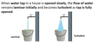
Reynolds Number: Reynolds Number is the ratio of Inertial forces to the Viscous forces. By knowing this number, one can describe the flow whether the flow is laminar, turbulent or transitional flow. There are three possibilities of the range of Reynolds Number: If Reynolds number < 2100 or 2300 ⟺ Laminar Flow If Reynolds number > 4000 ⟺ Turbulent Flow If 2300 < Reynolds number < 4000 ⟺ Transitional Flow In case of different shapes other than circle, the formula for Reynolds Number remain the same however diameter involves in the formula become Hydraulic Diameter which is given by: For pipe: Critical Reynolds Number ⟾ The Reynolds number at which the flow becomes turbulent Re cr For different shapes, the hydraulic diameters are given by: Completely Filled Flow In Closed Channel: If pipe is is considered to filled completely with closed channel, then following are the conditions which...
Heat exchangers move thermal energy from one fluid to another without letting the fluids mix. They sit in nearly every process, power and utility system, from crude preheat trains to lube oil coolers. Getting one right means getting the thermal duty, the pressure drop and the mechanical design right together. This post covers the fundamentals, the key equations, a worked sizing example and the checks engineers apply before releasing a design. Tube bundle of a shell-and-tube heat exchanger. Photo by Alnitak3/Wikimedia Commons , licensed CC BY-SA 4.0 . Heat Exchanger Fundamentals Heat flows from the hot stream through a wall to the cold stream. Three resistances act in series: convection on the hot side, conduction through the tube or plate wall, and convection on the cold side. Fouling layers add resistance on each surface over time. The designer's job is to provide enough surface area to transfer the required duty with acceptable pressure drop and cost. Type Strengths Limits...
Intersection Of Solids: Solids are obtained by the combination of of two or more basic solids. When two or more solids combine, a definite curve/line is seen at their intersection. This curve/line is called curve/line of intersection (COI / LOI) and it is the result of inter-penetration of solids. Applications Of Intersection Of Solids: Designing a sheet metal objects. Automobile Parts. Moulding patterns. Forged end of connecting road. Intersection of two contacting surface, etc. Inter-Penetration Of Solids: When one solids penetrates another solids then their surfaces intersect and at the junction of intersection a typical curve is formed, which remains common to both solids. This curve is called Curve of Intersection and it is a result of inter-penetration of solids. Cases Of Intersection Of Solids: First we need to discuss the general solution steps of how we draw intersection of solids diagram. So know, we are going to discuss the basic steps:...




Comments
Post a Comment
Questions or corrections are welcome. Please mention the relevant section and units. Do not post confidential project data or personal contact details. For project inquiries, use the Fluxiss contact page.