Every shell-and-tube exchanger is sized against one number: the mean temperature difference that drives heat across the tubes. The log mean temperature difference, with a correction factor for multi-pass layouts, is the standard way to get it. This post answers the five questions engineers search for most, then sizes a one-shell-pass, four-tube-pass oil cooler step by step. It builds on our overview of heat exchangers . A shell-and-tube exchanger bundle being pulled with a bundle extractor. Photo: CEphoto, Uwe Aranas, CC BY-SA 3.0, via Wikimedia Commons . When to use the LMTD method? Use the LMTD method when the inlet and outlet temperatures of both streams are known or fixed by the process, and the unknown is the area. That is the normal situation in exchanger design: the duty Q follows from the flow, specific heat and temperature change, and the area from Q = U A F ΔT lm . When the outlet temperatures are unknown, as when rating an existing exchanger, the NTU method is easier, b...
Get link
Facebook
X
Pinterest
Email
Other Apps
NPSH Available Calculation: NPSHa Formula, NPSH Margin and Suction Lift Worked Example
Get link
Facebook
X
Pinterest
Email
Other Apps
-
Cavitation is one of the most common causes of early pump failure, and it is almost always a suction-side problem. The check is simple in principle: the pressure available at the pump inlet must stay above the pressure at which the liquid begins to vaporise, with enough margin to cover uncertainty. This post answers the five questions engineers search for most, then works through a suction lift example. It builds on our introduction to pumps and turbomachinery.
What is the formula for calculating the NPSH value?
For a pump taking suction from a vessel or sump, the net positive suction head available is the absolute pressure head at the liquid surface, minus the vapour pressure head, plus the static height, minus the suction line losses:
NPSHa = (ps − pv) / (ρ g) + z − hf
Here ps is the absolute pressure on the liquid surface (atmospheric for an open tank), pv is the vapour pressure at pumping temperature, z is the height of the liquid surface above the pump centreline (negative for a suction lift), and hf is the friction and fitting loss in the suction line.
Friction uses the Darcy–Weisbach equation, hf = f (L/D) v²/2g + Σ K v²/2g, with f from the friction chart; see our posts on viscous flow in pipes and chilled water pipe sizing for the method. Compare NPSHa with NPSHr, which comes from the vendor's pump curve and is a property of the pump, not the system. Cavitation begins when NPSHa falls below what the impeller inlet needs.
What is NPSH required and available?
NPSH available (NPSHa) is what the system supplies at the pump suction: the net positive suction head above vapour pressure, set by atmospheric pressure, liquid level, temperature and the suction line. NPSH required (NPSHr) is what the pump needs to avoid performance loss, and the vendor publishes it on the pump curve against flow. In API 610 and the Hydraulic Institute standards, NPSHr is defined as NPSH3, the value at which the head drops 3%, which is a measurable reference point and not the onset of cavitation. The difference NPSHa − NPSHr is the NPSH margin, and ANSI/HI 9.6.1 gives recommended margin ratios that depend on the application and on suction energy. Pump head stays unaffected until NPSHa approaches NPSHr, then the curve falls away.
How to calculate suction lift of pump?
Suction lift is the vertical distance from the liquid surface down to the pump centreline when the liquid is below the pump. Rearrange the NPSHa equation for the largest lift that keeps NPSHa at the required level: zlift,max = (patm − pv) / (ρ g) − hf − NPSHrequired with margin. At sea level with cold water the atmosphere can in theory support about 10 m, but friction, vapour pressure and NPSHr reduce this to a few metres, and air release makes the practical limit lower. The pump sees the lift as a vacuum at its suction flange equal to the lift plus the losses. Pump sizing must therefore include the lift in the head calculation and the suction pipe in the NPSH check.
What happens if NPSH is too low?
When NPSHa falls below NPSHr, vapour bubbles form at the impeller eye and collapse as pressure rises through the vane, causing noise, vibration, pitting of the impeller and loss of head. The pump suction head falls, the pump curve drops away, flow becomes unstable, and seals and bearings suffer. The damage depends on how far below, and for how long, the pump runs there. Typical fixes are to raise the liquid level or lower the pump, cool the liquid, enlarge the suction line, remove fittings and restrictions, reduce flow, or choose a pump with lower NPSHr. In every case the NPSH margin must be restored; never throttle the suction line to control flow.
Calculate it from the system as in the worked example below, using the lowest liquid level, highest temperature and highest flow, because those give the minimum NPSHa. For cooling tower pumps the basin level above the pump centreline is small and the water warm, so NPSHa is often only a few metres and the suction line deserves care. In an existing system, measure it: read the suction pressure at the flange with a gauge, convert to absolute pressure head, add the velocity head and subtract the vapour pressure head. Vendors confirm NPSHr by an NPSH test, in a closed loop where a vacuum pump lowers the suction pressure until head falls 3%. Plot NPSHa and NPSHr against flow on the pump curve; the NPSH margin is the gap between them.
Worked Example: Suction Lift on a Water Pump
A centrifugal pump delivers 25 L/s of water at 40 °C from an open sump. The liquid surface is 3.0 m below the pump centreline. The suction line is DN150 Sch 40 steel (inside diameter 154.1 mm) with 12 m of straight pipe, a foot valve (K = 2.0), one elbow (K = 0.3) and an eccentric reducer (K = 0.1). Atmospheric pressure is 101.3 kPa, water vapour pressure at 40 °C is 7.38 kPa, density is 992.2 kg/m³ and viscosity is 0.653 mPa·s. The vendor's curve gives NPSHr = 3.5 m at this flow (assumed).
Step
Calculation
Result
Velocity
0.025 / (π/4 × 0.1541²)
v = 1.34 m/s
Reynolds number and f
Re = 313,800, ε = 0.046 mm
f = 0.0170
Straight pipe loss
0.0170 × (12 / 0.1541) × 1.34² / (2 × 9.81)
0.12 m
Fittings loss
2.4 × 0.0915
0.22 m
Suction line loss
0.12 + 0.22
hf = 0.34 m
Pressure head
(101.3 − 7.38) × 1,000 / (992.2 × 9.81)
9.65 m
NPSHa
9.65 − 3.0 − 0.34
6.31 m
NPSH margin
6.31 − 3.5, and 6.31 / 3.5
2.81 m, ratio 1.80
The suction flange would read about −(9.73 × 3.34 + 0.89) = −33.4 kPa gauge. Temperature matters: at 70 °C the vapour pressure is about 31.2 kPa and the density 977.8 kg/m³, so the pressure head falls to 7.31 m and NPSHa to about 3.97 m, a ratio of only 1.13 (friction taken as unchanged). At 1,500 m altitude, with atmospheric pressure of about 84.6 kPa and 40 °C water, NPSHa is 4.59 m. Requiring NPSHa = 1.3 × 3.5 = 4.55 m gives a theoretical maximum lift of 9.65 − 0.34 − 4.55 = 4.76 m, but practical lifts stay lower so the pump primes and air releases.
Practical Checks
Worst case: use the lowest level, highest temperature and maximum flow, with an allowance for a dirty strainer.
Suction line: keep it short, straight and large enough for low velocity, with no elbows close to the inlet.
Air pockets: fit eccentric reducers flat side up and avoid high points that trap air.
Runout flow: check the margin at the highest flow, since NPSHr rises with flow.
Vessel pressure: for a pressurised or vacuum vessel, use the real surface pressure, not atmospheric.
Records: document levels, temperature, vapour pressure source and site altitude, so the calculation can be reviewed.
How Fluxiss Approaches Pump Suction Design
Fluxiss is a multidisciplinary engineering consultancy serving oil and gas, power and maritime clients. Its piping team lays out pump suction lines and checks NPSH margin alongside the isometrics and stress analysis, so the layout supports the pump's requirements.
Frequently Asked Questions
Does NPSHa change with flow?
Yes. Friction loss rises with flow, so NPSHa falls as flow increases while NPSHr rises.
Why is NPSH given as head?
Pump head is stated in metres of the pumped liquid, so NPSH uses the same units and the pump curve applies to any density.
Can I raise NPSHa by pressurising the tank?
Yes. Raising the surface pressure raises NPSHa directly, provided the vessel is rated for it.
What margin is enough?
It depends on the application and suction energy. Use ANSI/HI 9.6.1 and the project specification, and note that API 610 uses NPSH3.
Need pump suction piping and NPSH support?
Fluxiss provides 3D piping layout and isometrics for process and utility systems, including pump suction lines laid out for NPSH margin. Send your pump data and layout, and the team can advise on the design.
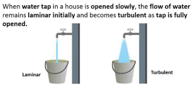
Reynolds Number: Reynolds Number is the ratio of Inertial forces to the Viscous forces. By knowing this number, one can describe the flow whether the flow is laminar, turbulent or transitional flow. There are three possibilities of the range of Reynolds Number: If Reynolds number < 2100 or 2300 ⟺ Laminar Flow If Reynolds number > 4000 ⟺ Turbulent Flow If 2300 < Reynolds number < 4000 ⟺ Transitional Flow In case of different shapes other than circle, the formula for Reynolds Number remain the same however diameter involves in the formula become Hydraulic Diameter which is given by: For pipe: Critical Reynolds Number ⟾ The Reynolds number at which the flow becomes turbulent Re cr For different shapes, the hydraulic diameters are given by: Completely Filled Flow In Closed Channel: If pipe is is considered to filled completely with closed channel, then following are the conditions which...
Intersection Of Solids: Solids are obtained by the combination of of two or more basic solids. When two or more solids combine, a definite curve/line is seen at their intersection. This curve/line is called curve/line of intersection (COI / LOI) and it is the result of inter-penetration of solids. Applications Of Intersection Of Solids: Designing a sheet metal objects. Automobile Parts. Moulding patterns. Forged end of connecting road. Intersection of two contacting surface, etc. Inter-Penetration Of Solids: When one solids penetrates another solids then their surfaces intersect and at the junction of intersection a typical curve is formed, which remains common to both solids. This curve is called Curve of Intersection and it is a result of inter-penetration of solids. Cases Of Intersection Of Solids: First we need to discuss the general solution steps of how we draw intersection of solids diagram. So know, we are going to discuss the basic steps:...
Types Of Lines And Its Uses: There are three types of types on the basis of thickness and they are: Visible Lines ↝ It represents features that can be seen in the current view. Hidden Lines ↝ It represents features that cannot be seen in the current view. Center Line ↝ It represents symmetry, path of motion, centers of circles,, axis of asymmetrical parts. Dimension and Extension Lines ↝ It indicates the sizes and location of features on a drawing. Placement Of Dimension Lines: Dimension should be outside the view. Dimension should be applied to one view. Dimension should be placed in a view that shows the distance in its true length. Dimension lines should be placed, in general 10 mm (1/2 in) away from the outlines from the view. Parallel lines should be placed uniformly. Values should be midway (auto centered) between the arrow heads, except when a center-line interferes. Dime...




Comments
Post a Comment
Questions or corrections are welcome. Please mention the relevant section and units. Do not post confidential project data or personal contact details. For project inquiries, use the Fluxiss contact page.