View Factor Orientation (or View factor or shape factor) plays an important role in radiation heat transfer. View factor is defined as, "fraction of radiation leaving surface 'i' and strike 'j' ". Summation Rule (View Factor) If there is are similar surfaces 'i' and 'j' , then: Blackbody Radiation Exchange Radiation Exchange between Opaque, Diffuse, Gray surfaces in an Enclosure 1. Opaque 2. Surfaces 3. Two surface enclosure Radiation Shield It is used to protect surfaces from radiation act like a reflective surface. References: Material from Class Lectures + Book named Fundamentals of Heat and Mass Transfer by Theodore L. Bergman + My knowledge. Photoshoped pics are developed. Some pics and GIF from Google. Videos from YouTube ( Engineering Sights ).
Get link
Facebook
X
Pinterest
Email
Other Apps
Turbomachinery_Pumps
Get link
Facebook
X
Pinterest
Email
Other Apps
-
Turbomachinery
It is defined as, "a dynamic fluid machine that adds energy to or extracts energy from the fluid".
Mechanical energy of rotation (rotation) ←Transfer→ fluid flow energy.
Mainly deals with two turbomachine pumps and turbine.
Usually a motor exerts a torque by using blades to force the fluid to move.
Turbines(which is the source of power):
Which extracts energy from the working fluid.
Fluid pushes the machine and produce shaft power.
Classification On The Basis Of Flow Direction
Turbomachines are classified on the basis of flow directions:
Radial Flow machine ↔ fluid flows in radial direction.
Axial Flow machine ↔ fluid flows along component axis.
Mixed Flow machine ↔ some machine have both radial and axial components.
Working Principle
During the fluid-blade interaction, either the fluid is pushed or the blade is pushed due to which energy transfer takes place which will increase/decrease fluid stream velocity.
Pump ↔ Velocity is increased in the direction of the rotation of the rotor.
Turbine ↔ Velocity is increased in the direction opposite to the rotation of the rotor.
High speed rotating impeller throws the incoming liquid radially outward due to centrifugal effect.
There are 2 main components of centrifugal pump:
Impeller (Rotating) ↔ rotates and throws fluid outward.
Casing with a Volute Chamber (Stationary) ↔ fluids impart energy with increasing area.
Working Principle
As impeller rotates, the fluid at the center is impelled outwards due to centrifugal force.
Empty spaces creates a suction (or negative) pressure for the incoming fluid, which fills the center space.
The fluid is discharged into the purposefully designed volute chamber (Velocity reduced, Pressure increased as Area increased) to overcome pumping system resistance.
Priming ↔ filling all the part up with water before it is started (initiates working).
Centrifugal Pump Configurations
Centrifugal pumps are divided into the following types:
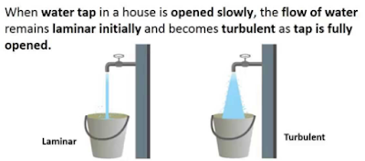
Reynolds Number: Reynolds Number is the ratio of Inertial forces to the Viscous forces. By knowing this number, one can describe the flow whether the flow is laminar, turbulent or transitional flow. There are three possibilities of the range of Reynolds Number: If Reynolds number < 2100 or 2300 ⟺ Laminar Flow If Reynolds number > 4000 ⟺ Turbulent Flow If 2300 < Reynolds number < 4000 ⟺ Transitional Flow In case of different shapes other than circle, the formula for Reynolds Number remain the same however diameter involves in the formula become Hydraulic Diameter which is given by: For pipe: Critical Reynolds Number ⟾ The Reynolds number at which the flow becomes turbulent Re cr For different shapes, the hydraulic diameters are given by: Completely Filled Flow In Closed Channel: If pipe is is considered to filled completely with closed channel, then following are the conditions which...
View Factor Orientation (or View factor or shape factor) plays an important role in radiation heat transfer. View factor is defined as, "fraction of radiation leaving surface 'i' and strike 'j' ". Summation Rule (View Factor) If there is are similar surfaces 'i' and 'j' , then: Blackbody Radiation Exchange Radiation Exchange between Opaque, Diffuse, Gray surfaces in an Enclosure 1. Opaque 2. Surfaces 3. Two surface enclosure Radiation Shield It is used to protect surfaces from radiation act like a reflective surface. References: Material from Class Lectures + Book named Fundamentals of Heat and Mass Transfer by Theodore L. Bergman + My knowledge. Photoshoped pics are developed. Some pics and GIF from Google. Videos from YouTube ( Engineering Sights ).
Mechanical Injection System: Used to inject fuel into the combustion chamber. Fuel speed > air speed at delivery point to atomize fuel. Amount of fuel delivered into the air stream going into the engine is controlled by pump which forces the fuel under pressure. A device used to initiate and control the combustion process is called Mechanical Injection System. Functional Requirements of Injection System: Metering of Fuel: Used to control fuel to meet speed and load requirements of the engine. Injection Timing: Have proper injection timing to obtain max. power, fuel economy and proper burning. It is done by Camshaft or Push rod (Rocker Arm) Mechanism . Proper Control of Injection Rate: To get desired heat release pattern during combustion. Proper Atomization of Fuel: Proper making of droplets to make best Air/Fuel mixture. Proper Spray Pattern: Distribution of droplets to ensure rapid mixing of fuel & air. Uniform Distribut...



Comments
Post a Comment
HI, we wI'll contact you later