View Factor Orientation (or View factor or shape factor) plays an important role in radiation heat transfer. View factor is defined as, "fraction of radiation leaving surface 'i' and strike 'j' ". Summation Rule (View Factor) If there is are similar surfaces 'i' and 'j' , then: Blackbody Radiation Exchange Radiation Exchange between Opaque, Diffuse, Gray surfaces in an Enclosure 1. Opaque 2. Surfaces 3. Two surface enclosure Radiation Shield It is used to protect surfaces from radiation act like a reflective surface. References: Material from Class Lectures + Book named Fundamentals of Heat and Mass Transfer by Theodore L. Bergman + My knowledge. Photoshoped pics are developed. Some pics and GIF from Google. Videos from YouTube ( Engineering Sights ).
Get link
Facebook
X
Pinterest
Email
Other Apps
Orthographic Projections
Get link
Facebook
X
Pinterest
Email
Other Apps
-
Projection:
The term Projection is defined as:
Presentation of an image or an object on a surface.
The principles used to graphically represent 3-D objects and structures on 2-D media and it based on two variables:
Line of Sight.
Plane of Projection.
Line of Sight & Plane of Projection:
Line of sight is divided into 2 types:
Parallel Projection
Converging Projection
&
A plane of projection is an imaginary flat plane upon which the image created by the lines of sight is projected.
Orthographic Projection:
When the projectors are parallel to each other and perpendicular to the plane of projection.
The lines pf sight of the observer create a view on the screen.
The screen is referred to as the Plane of Projection (POP).
The lines of sight are called Projection lines or projectors.
Rules of Orthographic Projection:
Edges that are parallel to a plane of projection appear as lines.
Edges that are inclined to a plane of projection appear as foreshortened lines.
Curved edges project as straight lines on the plane of projection to which they are perpendicular.
Curved edges project as curved lines on the planes to which they are parallel or inclined.
Normal surfaces appear as an edge in two opposite principal views, and appear as surface in all other principal views.
Inclined surfaces appear as an edge in two opposite principal views, and appear foreshortened in all other principal views.
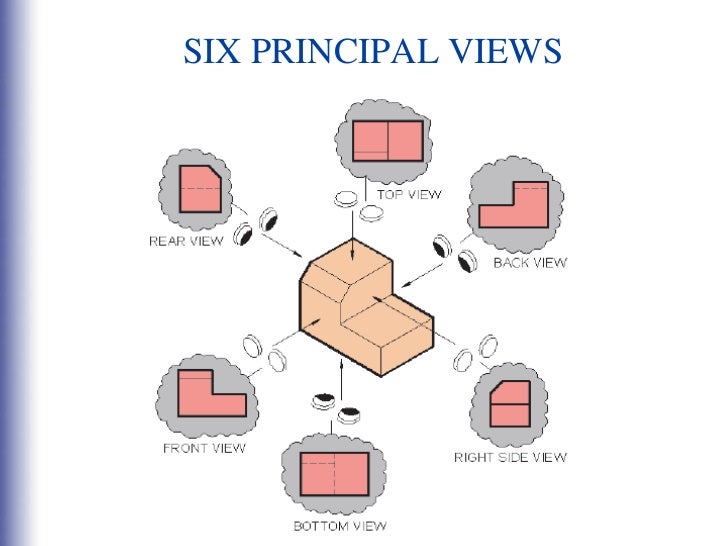
Six Principal Views of Orthographic Projection:
Six principal view of orthographic projection are:
How We Draw Views Of Orthographic Projection:
The figure shows how we draw views of orthographic projection and co-relate them with each other.
How We Choose The Front View:
It is the most important step taken when you start to draw views of Orthographic Projections. You should follow guidelines to get your path correct.
Front view should have minimum hidden lines.
The view should be stable.
Most basic profile should be used.
Types Of Projections:
There are two types of projections, namely:
First Angle Projection
Third Angle Projection
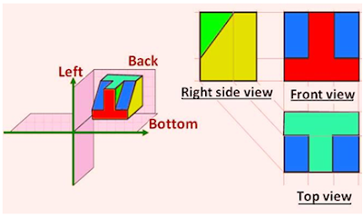
1. First Angle Projection:
2. Third Angle Projection:
Symbols Of Angles of Projections:
You should draw these symbols if you are going to draw views of Orthographic Projection.
Advance High Strength Steel Conventional low carbon mild steel has simpler ferritic structure (α-iron) and good ductility. Common type of HSS is High Strength Low Alloy (HSLA) ⇥ has yield strength 550 - 690 N/sq.mm . Manganese ⇥ supporter (stabilizer) of ferrite. Conventional HSS : Is single-phase ferritic steel with a potential for some pearlite in C-Mn steel. Lower strain hardening capacity. Advance HSS : primarily steel with a microstructure containing a phase other than ferrite, pearlite, cementite. Higher strain hardening capacity. Case Study of Automobile There are three different zones in a car: Crumple Zone (Front & Back) Middle Compartment Safety Cage Some important points about these zones are: Crumple Zone ⇥ Made with those materials which absorb maximum amount of energy. Safety Cage ⇥ Multiple areas (like cabins, structural elements). Areas of Safety cage are described ahead: Cabins (Blue Areas) ⇥ Should have high streng...
Gear Forming by Machining Formation of gear through machining consists of following methods: Form Milling by Disc Cutter Form Milling by End Mill Cutter Shaper, Planner and Slotter Broaching 1. Form Milling by Disc Cutter It is defined as, " Tooth is cut one by one by plunging the rotating cutter into the blank " . Each gear needs a separate cutter. 8 - 10 standard cutters are available for producing 12 - 120 teeth gears. Used for big spur gears of large pitch. 2. Form Milling by End Mill Cutter It includes the cutting of tooth at a time and then indexed for the next tooth space for cutting. For a small volume production of low precision gears. Set of 10 cutters ↠ 12 - 120 teeth gears . Used for teeth of large gears/module. To reduce cost, same cutter is often used for multiple sized gears resulting in profile errors . Characteristics: Use of Hardened stainless steels (HSS) form milling cutters. Use of Ordinary milling machines. Low production rate (need of indexing...


Comments
Post a Comment
HI, we wI'll contact you later