Every nozzle cut into a pressure vessel shell removes metal that was carrying load. ASME VIII Div. 1 handles this with the area replacement method: the metal removed must be put back within defined limits around the opening. This post walks through the method, explains when to use a reinforcing pad, a thicker neck or an insert plate, and works through a complete NPS 6 nozzle example. It builds on our wider guide to pressure vessel and storage tank design . Why an Opening Weakens a Shell A circular hole in a cylindrical shell under internal pressure creates a stress concentration. The peak stress at the edge of a plain hole is roughly 2.5 times the nominal hoop stress, and the hole interrupts exactly the metal that resists hoop stress. For a refresher on how a stress state resolves on different planes, see our note on stress transformation . The Code does not calculate the peak. It requires the removed metal to be replaced close to the opening, which keeps local stresses within the r...
Get link
Facebook
X
Pinterest
Email
Other Apps
Pump Nozzle Loads Under API 610: Checking Allowable Forces and Moments in CAESAR II
Get link
Facebook
X
Pinterest
Email
Other Apps
-
A centrifugal pump is only as good as the alignment between its shaft and its driver, and piping is one of the few things that can quietly destroy that alignment. This post explains how API 610 limits pump nozzle loads, how to model a pump in CAESAR II, and how to check and fix a hot-line case using a worked example.
Why Pump Nozzle Loads Matter
Every force and moment from the suction and discharge piping lands on the pump casing. Excess load distorts the casing, shifts the casing feet against the baseplate and moves the shaft relative to the driver. The result is misalignment, worn seals and bearings, coupling damage and shorter pump life. API 610 sets nozzle load limits so that shaft-end movement stays small, roughly 0.25 mm (0.010 in), once thermal growth and installation error are added. For background on how these machines develop head and flow, see our note on turbomachinery and pumps.
Base-mounted end-suction centrifugal pumps: every pipe load at the flanges is carried by the casing and baseplate. Photo: Bitjungle, CC BY-SA 4.0, via Wikimedia Commons.
API 610 Table 5 and Annex F
The nozzle loads table (Table 5 in the 11th edition; confirm the numbering in your edition) lists allowable forces and moments, Fx, Fy, Fz, Mx, My, Mz and their resultants, for each nozzle size up to NPS 16 on steel casings. Values depend on nozzle size and orientation, and API 610 defines the coordinate system to use. The pressure casing is designed to withstand twice the Table 5 loads. That margin allows Annex F to qualify loads above the table, but only with purchaser approval, and the standard warns that misalignment can be up to 50% greater than with Table 5 loads. For a horizontal pump, Annex F requires:
F.1.2.1: each individual force and moment component on a nozzle must not exceed 2 × its Table 5 value.
F.1 and F.2: FRSA / (1.5 FRST) + MRSA / (1.5 MRST) ≤ 2 for suction, and the same form for discharge. A is the applied value and T is the Table 5 value.
F.3: at the pump centre, FRCA ≤ 1.5 (FRST + FRDT).
F.4: MYCA ≤ 2.0 (MYST + MYDT).
F.5: MRCA ≤ 1.5 (MRST + MRDT).
The pump-centre values come from translating the nozzle loads to the pump centreline using the nozzle coordinates and the API 610 sign convention.
Modelling the Pump in CAESAR II
Place nodes at the suction and discharge flange faces and connect each to the pump centreline with rigid elements representing the casing.
Anchor the centreline node, with imposed displacements for casing thermal growth in the operating case.
Use the API 610 equipment compliance check, map each nozzle to the correct API axes and set the allowable load multiplier. Use 1.0 for a strict Table 5 check, or up to 2.0 where Annex F is accepted with vendor and purchaser approval.
Evaluate suction and discharge in the same load case, because the Annex F equations and pump-centre checks combine them.
Run the operating, sustained and standby cases. In standby, the casing is cold while the connected lines may be hot.
Thermal Growth, Cold Spring and Springs Near the Pump
Both the casing and the connected pipe grow with temperature, following ΔL = α × L × ΔT with α near 12 × 10-6 per °C for carbon steel. An OH2 pump is supported at the shaft centreline, so the casing grows up and outward from that line. With a nozzle 450 mm above the centreline and ΔT = 200 K, the nozzle rises about 1.1 mm. A 3 m vertical discharge riser over the same ΔT grows about 7 mm. If the support under it resists that growth, the difference goes straight into the nozzle.
Cold spring, where a pipe is deliberately fitted short to offset growth, is rarely used at pumps. It relies on fit-up accuracy that is hard to verify, and codes restrict the credit allowed. Prefer routing flexibility and well-chosen supports. A variable spring hanger near the nozzle carries pipe weight without loading the casing and without resisting thermal movement. For selection, spacing and guide placement, see our guide to pipe supports in process piping.
Closed cooling water pumps at Gebze power plant, where large-bore suction and discharge lines need flexible routing and supports to keep nozzle loads within limits. Photo: Harald the Bard, CC BY-SA 4.0, via Wikimedia Commons.
Worked Example: OH2 Pump on a Hot Line
An OH2 end-suction pump handles hydrocarbon at 220 °C, with an NPS 8 suction and an NPS 6 top discharge. The discharge rises 3 m before turning to a header. The Table 5 resultants below are assumed for illustration only. Use the values from your API 610 edition or the vendor datasheet on a real project.
First run, as routed. Suction applied loads are 5,200 N and 3,400 N·m, so the F.1 sum is 5,200 / 6,750 + 3,400 / 3,450 = 0.77 + 0.99 = 1.76, which passes. Discharge applied loads are 5,900 N and 3,900 N·m, so the F.2 sum is 5,900 / 4,950 + 3,900 / 2,550 = 1.19 + 1.53 = 2.72, which fails. At the pump centre, the limits are 1.5 × (4,500 + 3,300) = 11,700 N for force and 1.5 × (2,300 + 1,700) = 6,000 N·m for moment.
The fix. The rigid rest under the first discharge elbow was resisting riser growth. The fix replaced it with a variable spring hanger on the riser, added a 600 mm offset leg before the header and moved the first guide further from the nozzle. After the re-run, discharge applied loads fell to 2,900 N and 1,900 N·m, and suction loads to 3,600 N and 2,000 N·m.
Check
Limit
As routed
After fix
Suction, F.1 sum
≤ 2
1.76 (pass)
1.11 (pass)
Discharge, F.2 sum
≤ 2
2.72 (fail)
1.33 (pass)
Pump-centre force, F.3
≤ 11,700 N
8,400 N (pass)
6,800 N (pass)
Pump-centre moment, F.5
≤ 6,000 N·m
7,100 N·m (fail)
4,900 N·m (pass)
The F.1.2.1 component check and the F.4 moment check must also pass in the software report.
Practical Engineering Checks
Confirm the allowables: API 610 pumps use Table 5, while non-API pumps often have lower vendor limits, or follow ANSI/HI 9.6.2.
Check axes and signs: the loads on the pump are the reactions from the piping, and each nozzle has its own API axis orientation.
Cover every operating mode: include start-up, upset, steam-out, standby and hydrotest weight.
Support weight near the nozzle: avoid letting strainer, valve and elbow weight sit on the casing.
Take care with expansion joints: pressure thrust can load the nozzle unless the joint is anchored or tied.
Protect suction hydraulics: flexibility changes must not add friction losses that cut NPSH margin. For the basics, see viscous flow in pipes.
Get approvals in writing: record vendor and purchaser acceptance of 2 × Table 5 or Annex F use.
Re-check after changes: layout revisions and as-built conditions can change nozzle loads.
How Fluxiss Approaches Pump Nozzle Checks
Fluxiss is a multidisciplinary engineering consultancy. Its pipe stress analysis work treats equipment nozzle loads as part of the same model as supports and flexibility, so a fix at the pump is checked against the rest of the line.
Frequently Asked Questions
Can I always use 2 × Table 5 for pump nozzles?
No. Annex F allows loads above Table 5 only when its combined criteria are met and the purchaser approves. Vendor confirmation should be obtained early.
Do I check suction and discharge separately?
Check each nozzle, then check both together at the pump centre. The Annex F equations combine them, so both must be evaluated in the same load case.
Is cold spring a good fix for high pump nozzle loads?
Usually not. It depends on fit-up accuracy that cannot be easily verified, and codes limit the credit taken. Reroute or change supports first.
What if the pump is not API 610?
Use the vendor's allowable loads, or ANSI/HI 9.6.2 where the project specifies it. These values are often lower than API 610.
Need pump nozzle load checks?
Fluxiss provides pipe stress analysis that includes equipment nozzle load checks, support design and reporting for oil and gas, power and industrial projects. Share your pump data and line layout, and the team can review nozzle loads against API 610 or vendor allowables.
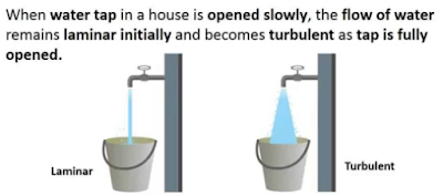
Reynolds Number: Reynolds Number is the ratio of Inertial forces to the Viscous forces. By knowing this number, one can describe the flow whether the flow is laminar, turbulent or transitional flow. There are three possibilities of the range of Reynolds Number: If Reynolds number < 2100 or 2300 ⟺ Laminar Flow If Reynolds number > 4000 ⟺ Turbulent Flow If 2300 < Reynolds number < 4000 ⟺ Transitional Flow In case of different shapes other than circle, the formula for Reynolds Number remain the same however diameter involves in the formula become Hydraulic Diameter which is given by: For pipe: Critical Reynolds Number ⟾ The Reynolds number at which the flow becomes turbulent Re cr For different shapes, the hydraulic diameters are given by: Completely Filled Flow In Closed Channel: If pipe is is considered to filled completely with closed channel, then following are the conditions which...
Intersection Of Solids: Solids are obtained by the combination of of two or more basic solids. When two or more solids combine, a definite curve/line is seen at their intersection. This curve/line is called curve/line of intersection (COI / LOI) and it is the result of inter-penetration of solids. Applications Of Intersection Of Solids: Designing a sheet metal objects. Automobile Parts. Moulding patterns. Forged end of connecting road. Intersection of two contacting surface, etc. Inter-Penetration Of Solids: When one solids penetrates another solids then their surfaces intersect and at the junction of intersection a typical curve is formed, which remains common to both solids. This curve is called Curve of Intersection and it is a result of inter-penetration of solids. Cases Of Intersection Of Solids: First we need to discuss the general solution steps of how we draw intersection of solids diagram. So know, we are going to discuss the basic steps:...
Types Of Lines And Its Uses: There are three types of types on the basis of thickness and they are: Visible Lines ↝ It represents features that can be seen in the current view. Hidden Lines ↝ It represents features that cannot be seen in the current view. Center Line ↝ It represents symmetry, path of motion, centers of circles,, axis of asymmetrical parts. Dimension and Extension Lines ↝ It indicates the sizes and location of features on a drawing. Placement Of Dimension Lines: Dimension should be outside the view. Dimension should be applied to one view. Dimension should be placed in a view that shows the distance in its true length. Dimension lines should be placed, in general 10 mm (1/2 in) away from the outlines from the view. Parallel lines should be placed uniformly. Values should be midway (auto centered) between the arrow heads, except when a center-line interferes. Dime...




Comments
Post a Comment
Questions or corrections are welcome. Please mention the relevant section and units. Do not post confidential project data or personal contact details. For project inquiries, use the Fluxiss contact page.