Every nozzle cut into a pressure vessel shell removes metal that was carrying load. ASME VIII Div. 1 handles this with the area replacement method: the metal removed must be put back within defined limits around the opening. This post walks through the method, explains when to use a reinforcing pad, a thicker neck or an insert plate, and works through a complete NPS 6 nozzle example. It builds on our wider guide to pressure vessel and storage tank design . Why an Opening Weakens a Shell A circular hole in a cylindrical shell under internal pressure creates a stress concentration. The peak stress at the edge of a plain hole is roughly 2.5 times the nominal hoop stress, and the hole interrupts exactly the metal that resists hoop stress. For a refresher on how a stress state resolves on different planes, see our note on stress transformation . The Code does not calculate the peak. It requires the removed metal to be replaced close to the opening, which keeps local stresses within the r...
Get link
Facebook
X
Pinterest
Email
Other Apps
Piping Design and Stress Analysis: A Practical ASME B31.3 Workflow
Get link
Facebook
X
Pinterest
Email
Other Apps
-
Piping design and stress analysis are two halves of one job. A layout that fits the plot plan can still fail in service: thermal growth can overload a pump nozzle, or a relief event can throw a line off its supports. This post walks through a practical ASME B31.3 workflow, from line list to support schedule. It is written for engineers who run the analysis and for project managers who need to know what to ask for.
Process piping network at the Rhineland refinery, Cologne. Photo: CEphoto, Uwe Aranas, CC BY-SA 3.0 via Wikimedia Commons
What Pipe Stress Analysis Is and When It Is Required
Pipe stress analysis checks that a piping system can carry pressure, weight, thermal expansion, wind, seismic, relief thrust and similar loads without overstressing the pipe, fittings, supports or connected equipment. It produces stresses to compare with code allowables, displacements to check for clashes, and the loads imposed on supports and nozzles.
B31.3 does not require every line to be formally analysed. Lines that duplicate a successfully operating system, or that can readily be judged adequate by comparison, may be accepted without calculation. Most projects therefore define a critical line list. Typical triggers are:
High or cyclic temperatures, and large-bore lines.
Connections to pumps, compressors, turbines and air coolers.
Relief and flare headers, and lines with slug or two-phase flow.
Long pipe rack runs and buried piping.
Agree the criteria early. It is the cheapest way to control stress scope and schedule.
The ASME B31.3 Stress Checks
B31.3 assesses three stress categories, each against its own allowable.
Check
Loads covered
Acceptance
Sustained (SL)
Pressure and weight
SL ≤ Sh (hot allowable stress)
Occasional
Sustained plus wind, seismic or relief loads
≤ k × Sh, with k = 1.33 for loads under 10% of operating time (1.2 under 1%)
Expansion (SE)
Thermal displacement stress range
SE ≤ SA = f[1.25Sc + 0.25Sh], or the form that uses unused sustained margin
Sustained and occasional stresses are primary: they are load-controlled and do not relax. Expansion stress is secondary and self-limiting, so it is checked as a range. The factor f reduces the allowable as the number of cycles increases. Confirm the exact equations and factors in the current code edition.
Design Inputs You Need Before Modelling
Most re-runs trace back to incomplete or outdated inputs. Collect these first:
P&IDs and line list: sizes, pipe class, service and insulation.
Conditions: design and operating pressures and temperatures, including upset and steam-out cases.
Material data: grades, corrosion allowance, and valve and flange weights.
Layout: the latest 3D model or isometrics.
Equipment data: nozzle locations, allowable loads and thermal growth.
Support and soil data: structural steel locations and, for buried lines, soil properties.
Special loads: wind, seismic, relief valve and slug data.
CAESAR II Modelling Workflow
Build the model from the latest layout, with nodes, sizes, schedules, materials, insulation and the weights of valves and flanges.
Enter loads: design and operating pressures and temperatures, fluid density and the hydrotest case.
Define load cases for sustained, operating, expansion and occasional conditions.
Run and review code compliance first, then displacements and restraint loads.
Iterate and document: adjust routing and supports with the layout team, then freeze the model and issue results.
Model quality decides result quality. Check the input echo and the plotted model against the layout before trusting any output.
Thermal Expansion and Flexibility
Thermal growth most often governs a layout. The basic relationship is ΔL = α × L × ΔT.
Worked example (carbon steel). Take a 30 m straight run between anchors. Assume α of about 12 × 10-6 per °C, an installation temperature of 20 °C and an operating temperature of 200 °C, so ΔT = 180 °C.
ΔL = 12 × 10-6 × 30,000 mm × 180 = about 65 mm
If that growth is fully restrained, the pipe develops stress of roughly E × α × ΔT. With E near 200 GPa, that is about 430 MPa, more than twice a typical carbon steel expansion allowable. The pipe needs flexibility, not extra strength. This is an illustration only; use the code's expansion data and project material properties for real work.
Flexibility normally comes from one of three sources:
Expansion loops (U, Z, L): the usual first choice, with no leak path and no maintenance, at the cost of plot space.
Direction changes: well-placed offsets between anchors often provide enough flexibility with no extra material.
Expansion joints: used when space or nozzle limits rule out a loop. They add pressure thrust, need guides and tie rods or anchors, and require maintenance, so avoid them in severe services where a loop will work.
Piping connections and supports on process equipment. Photo: Ivangiesen, CC0 via Wikimedia Commons
Supports, Restraints and Spring Hangers
Supports carry weight, control movement and protect equipment. Choose each by the job it must do:
Rest supports carry weight and allow sliding; check friction loads on the steel.
Guides limit lateral movement and are essential beside expansion joints.
Line stops and anchors restrain axial movement or fix the pipe completely.
Variable spring hangers support weight where vertical movement is modest, usually with load variation held near 25% or less.
Constant effort hangers suit large vertical movement or sensitive equipment.
Avoid supports that fight each other. A rigid support beside a spring hanger can leave the spring unloaded in the hot case. Check for uplift in every case, and give the structural team the calculated loads.
Nozzle Load Checks for Rotating Equipment
Equipment nozzles are often the tightest constraint. Excess piping load distorts casings, misaligns shafts and shortens equipment life. The usual references are:
API 610 for centrifugal pumps.
API 617 for compressors and expanders.
NEMA SM23 for mechanical-drive steam turbines.
Vendor allowables in the purchase specification may take priority, so confirm which set governs. For vessels, exchangers and tanks, local shell stresses at the nozzle need a separate check. If a nozzle fails, reroute for more flexibility first, then consider spring supports nearby. Ask the vendor for higher allowables only as a last step.
Common Mistakes
Starting late, so fixes arrive after the layout is frozen and steel is ordered.
Wrong temperature basis, such as ignoring steam-out or upset conditions that set the maximum.
Missing weights for insulation, valve operators or hydrotest fluid.
Ignoring equipment growth, which can exceed the pipe's own movement.
Over-restraining, which raises expansion stress and nozzle loads.
Weak change control, which lets the model drift from the layout.
Stress isometrics: marked-up drawings showing support types, locations and special requirements.
Support load schedule: loads for every restraint, for structural design.
Nozzle load summary: calculated loads against allowables.
Critical line list and status log: what was analysed, revision status and open items.
How Fluxiss Delivers Pipe Stress Analysis
Fluxiss is a multidisciplinary engineering consultancy. Piping stress analysis sits alongside piping layout, pressure vessels and tanks, and structural work, so analysis loads can feed support steel and equipment checks directly. The pipe stress analysis service follows the workflow above, from a critical line list and agreed design basis to stress isometrics, support loads and a report your project team can use.
Frequently Asked Questions
Does every line need a formal stress analysis under ASME B31.3?
No. The code allows lines to be accepted without calculation if they duplicate a successfully operating system or can readily be judged adequate by comparison. Most projects analyse only a critical line list defined by temperature, size, service and connected equipment.
What is the difference between sustained and expansion stress?
Sustained stress comes from continuous loads such as pressure and weight, and is limited to the hot allowable stress. Expansion stress comes from thermal displacement. It is a secondary stress, checked as a range against an allowable that depends on cold and hot allowable stresses and on cycle count.
When should I use an expansion joint instead of a loop?
Use one when there is no room for a loop or when the layout alone cannot meet nozzle loads. Remember the added pressure thrust, the need for guides and tie rods or anchors, and the maintenance burden. Loops are usually preferred for severe, toxic or high-pressure services.
Which standards govern pump and compressor nozzle loads?
API 610 applies to centrifugal pumps, API 617 to compressors and expanders, and NEMA SM23 to mechanical-drive steam turbines. Vendor allowables in the purchase specification may override these, so confirm which set applies before you start.
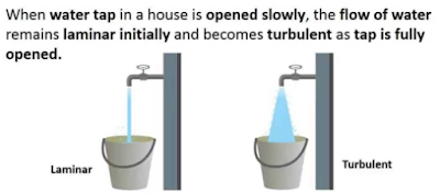
Reynolds Number: Reynolds Number is the ratio of Inertial forces to the Viscous forces. By knowing this number, one can describe the flow whether the flow is laminar, turbulent or transitional flow. There are three possibilities of the range of Reynolds Number: If Reynolds number < 2100 or 2300 ⟺ Laminar Flow If Reynolds number > 4000 ⟺ Turbulent Flow If 2300 < Reynolds number < 4000 ⟺ Transitional Flow In case of different shapes other than circle, the formula for Reynolds Number remain the same however diameter involves in the formula become Hydraulic Diameter which is given by: For pipe: Critical Reynolds Number ⟾ The Reynolds number at which the flow becomes turbulent Re cr For different shapes, the hydraulic diameters are given by: Completely Filled Flow In Closed Channel: If pipe is is considered to filled completely with closed channel, then following are the conditions which...
Intersection Of Solids: Solids are obtained by the combination of of two or more basic solids. When two or more solids combine, a definite curve/line is seen at their intersection. This curve/line is called curve/line of intersection (COI / LOI) and it is the result of inter-penetration of solids. Applications Of Intersection Of Solids: Designing a sheet metal objects. Automobile Parts. Moulding patterns. Forged end of connecting road. Intersection of two contacting surface, etc. Inter-Penetration Of Solids: When one solids penetrates another solids then their surfaces intersect and at the junction of intersection a typical curve is formed, which remains common to both solids. This curve is called Curve of Intersection and it is a result of inter-penetration of solids. Cases Of Intersection Of Solids: First we need to discuss the general solution steps of how we draw intersection of solids diagram. So know, we are going to discuss the basic steps:...
Types Of Lines And Its Uses: There are three types of types on the basis of thickness and they are: Visible Lines ↝ It represents features that can be seen in the current view. Hidden Lines ↝ It represents features that cannot be seen in the current view. Center Line ↝ It represents symmetry, path of motion, centers of circles,, axis of asymmetrical parts. Dimension and Extension Lines ↝ It indicates the sizes and location of features on a drawing. Placement Of Dimension Lines: Dimension should be outside the view. Dimension should be applied to one view. Dimension should be placed in a view that shows the distance in its true length. Dimension lines should be placed, in general 10 mm (1/2 in) away from the outlines from the view. Parallel lines should be placed uniformly. Values should be midway (auto centered) between the arrow heads, except when a center-line interferes. Dime...




Comments
Post a Comment
Questions or corrections are welcome. Please mention the relevant section and units. Do not post confidential project data or personal contact details. For project inquiries, use the Fluxiss contact page.