Every nozzle cut into a pressure vessel shell removes metal that was carrying load. ASME VIII Div. 1 handles this with the area replacement method: the metal removed must be put back within defined limits around the opening. This post walks through the method, explains when to use a reinforcing pad, a thicker neck or an insert plate, and works through a complete NPS 6 nozzle example. It builds on our wider guide to pressure vessel and storage tank design . Why an Opening Weakens a Shell A circular hole in a cylindrical shell under internal pressure creates a stress concentration. The peak stress at the edge of a plain hole is roughly 2.5 times the nominal hoop stress, and the hole interrupts exactly the metal that resists hoop stress. For a refresher on how a stress state resolves on different planes, see our note on stress transformation . The Code does not calculate the peak. It requires the removed metal to be replaced close to the opening, which keeps local stresses within the r...
Get link
Facebook
X
Pinterest
Email
Other Apps
Structural Engineering for Industrial Plants: Pipe Racks, Skids and Foundations
Get link
Facebook
X
Pinterest
Email
Other Apps
-
Industrial plants depend on structures that get little attention until something goes wrong: pipe racks carrying hundreds of lines, skids that must survive transport and lifting, and foundations that keep rotating machines aligned. Good industrial structural engineering design starts with a clear load path and early coordination with piping. This post covers the main decisions for pipe racks, skids and foundations.
Steel pipe rack erection at an industrial plant. Photo: PEO ACWA, CC BY 2.0 via Wikimedia Commons
Load Paths and Load Combinations
Every load follows a path from pipe to support, beam, column, foundation and soil. The structure is only as reliable as the load information at the start of that chain. The main load types are:
Load
Source
Design note
Dead
Steel, empty piping and equipment, insulation, fireproofing
Use realistic weights, not nominal allowances
Operating and test
Fluid contents, hydrotest water
Hydrotest often governs vertical pipe loads
Live
Platforms, access, maintenance
Per code and owner specification
Pipe thermal and friction
Anchor, guide and sliding support loads from stress analysis
Directional and case-specific
Wind and seismic
Structure, pipes, equipment
Seismic weight definition needs agreement
Dynamic
Machine vibration, relief thrust, slugs
May need dynamic analysis
Combinations follow the governing code, such as ASCE 7 (LRFD or ASD) or EN 1990, with owner amendments. Pipe loads need care because they are directional and tied to a specific operating case. Form combinations from individual load cases rather than from a single worst-case number. A line that pushes the rack one way in the hot case and pulls it back in the cold case should never be reduced to one enveloped force.
Multi-tier steel pipe rack carrying process piping. Photo: PEO ACWA, CC BY 2.0 via Wikimedia Commons
Pipe Rack Design
A pipe rack is a repeating frame system, so a few early decisions drive the whole design:
Frames: transverse bents with tiers sized for line count, and longitudinal bracing in braced bays. Bent spacing usually follows pipe support spans, and 6 m is common.
Future capacity: the design basis normally sets a spare allowance for future lines. Changing it later means re-checking everything, including foundations.
Longitudinal loads: friction at sliding supports equals the friction coefficient times the vertical load, often taken as 0.3 for steel on steel. Anchors and guides deliver larger point loads that must go into braced bays.
Long racks: the rack itself expands, so locate braced bays near the middle and provide movement joints where needed.
Wind and seismic: include wind on insulated pipes and multiple tiers. For seismic, ASCE 7 Chapter 15 covers nonbuilding structures.
Serviceability: set deflection and drift limits in the design basis, tighter where pipes are sensitive to sag or where lines connect to sensitive equipment.
Equipment Skids and Lifting
A skid is a small structure with a demanding job. It must keep equipment aligned in service, survive transport and lift safely.
Limit frame deflection so rotating equipment stays within alignment tolerances.
Analyse lifting with sling angles, centre of gravity (with a tolerance), spreader beams and a dynamic factor set by project criteria.
Check lifting lugs locally, including the pad eye, welds and shackle.
Include transport loads for road, rail or sea, with tie-down or sea-fastening points where required.
Check operating load cases, including nozzle loads from connected piping.
Steel Connections
Connections are where many structural problems start. AISC 360 Chapter J is the usual basis for bolted and welded joints. Typical connection types are:
Simple shear connections for beams.
Moment connections for rack bents and frames.
Gusset plates for bracing, checked for effects such as Whitmore width and block shear.
Base plates and anchor bolts, with anchorage checked under ACI 318 Chapter 17.
State in the design basis who designs connections, and make sure the forces used match the analysis model. Standardising a small set of connection types usually reduces fabrication cost and review time. Specify the coating or galvanizing system early too, because it affects bolt choice, hole sizes and site assembly.
Equipment and Machine Foundations
Static foundations support vessels, tanks and exchangers. Check bearing, sliding, overturning, uplift and settlement against the geotechnical report, and choose between spread footings and piles. ACI 318 governs the concrete design.
Machine foundations for compressors, pumps and turbines are a different problem. Dynamic behaviour matters more than strength:
Use a block or table-top foundation according to the machine type and vendor requirements.
Run a modal analysis, including soil stiffness, and keep natural frequencies away from operating speeds. A separation of at least 20% is a common target, but follow the vendor criteria.
Check vibration amplitudes against vendor limits. ACI 351.3R is the usual guidance document for dynamic equipment foundations.
Treat mass-ratio rules of thumb as a starting point only.
Detail anchor bolts, grout and embedments for the machine and baseplate.
Codes and Design Basis
Typical code sets are AISC 360 for steel, ASCE 7 for loads and ACI 318 for concrete. Projects using European standards apply EN 1990 for basis of design and loads, EN 1993 for steel, EN 1992 for concrete, EN 1997 for geotechnical work and EN 1998 for seismic. Local regulations and owner specifications always sit on top. Write the chosen codes, load criteria, materials and deflection limits into one design basis document before modelling starts, and have the owner approve it. Disputes about criteria are far cheaper to settle before the first model is built.
Analysis Tools
STAAD.Pro, SAP2000 and RISA are widely used for frame analysis. They calculate quickly, but the quality of the result depends on the model. Verify support conditions, member releases and load application, check that reactions balance the applied loads, and back up key results with hand checks. Review warnings and unstable-joint messages rather than clearing them, since they often point to a missing restraint or release.
Coordinating with Piping and Stress Loads
The handover between piping stress and structural teams is where schedules slip. Ask for a support load schedule that lists loads by case: weight, operating, hydrotest, thermal, friction and occasional. Include anchors and guides in all three directions. Agree a load transfer date and a revision procedure, so structural models are updated whenever support positions or loads change. If a stiff structure affects piping flexibility, include its stiffness in the stress model. Where a support lands on a rack beam away from a column, confirm the local beam check as well as the frame check.
Common Mistakes
Using single envelope loads for pipe forces that act in different directions.
Leaving out hydrotest weight, friction forces or future line allowances.
Working from outdated support loads after a layout change.
Leaving connection design unassigned between engineer and fabricator.
Skipping a frequency check for dynamic equipment foundations.
Ignoring uplift and overturning at foundations under wind or seismic cases.
Deliverables to Expect
Design basis and calculation package: codes, criteria, load combinations and results.
Framing plans and elevations: member sizes, bracing and connection types.
Foundation drawings: footings, piles, pedestals and anchor bolt plans.
Skid drawings and lifting calculations: including lug details and rigging arrangement.
Load summaries and material take-offs: support reactions for civil design and steel quantities for procurement.
How Fluxiss Delivers Structural Engineering
Fluxiss is a multidisciplinary engineering consultancy. Structural work sits alongside piping and stress analysis, pressure vessels and tanks, and MEP, so load information moves between disciplines without being retyped. The structural engineering service covers design bases, analysis, drawings and calculation packages for industrial and energy projects.
Frequently Asked Questions
What loads should a pipe rack be designed for?
Dead, operating, hydrotest, live, wind and seismic loads, plus pipe thermal and friction loads from the stress analysis. Add future line allowances and any dynamic or construction loads defined in the design basis.
How do piping and structural teams share loads?
Through a support load schedule giving loads by case and direction for each support, anchor and guide. Both teams should agree transfer dates and use a controlled revision process.
When does an equipment foundation need dynamic analysis?
Whenever the machine produces significant dynamic forces, as with compressors, large pumps and turbines. A modal check confirms natural frequencies are safely separated from operating speeds, as required by the vendor.
Do AISC, ASCE and ACI have to be used together?
Not necessarily. They are a common US-based set, but projects may use Eurocodes or national codes. What matters is a consistent code set recorded in the design basis and accepted by the owner.
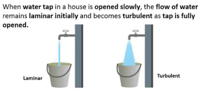
Reynolds Number: Reynolds Number is the ratio of Inertial forces to the Viscous forces. By knowing this number, one can describe the flow whether the flow is laminar, turbulent or transitional flow. There are three possibilities of the range of Reynolds Number: If Reynolds number < 2100 or 2300 ⟺ Laminar Flow If Reynolds number > 4000 ⟺ Turbulent Flow If 2300 < Reynolds number < 4000 ⟺ Transitional Flow In case of different shapes other than circle, the formula for Reynolds Number remain the same however diameter involves in the formula become Hydraulic Diameter which is given by: For pipe: Critical Reynolds Number ⟾ The Reynolds number at which the flow becomes turbulent Re cr For different shapes, the hydraulic diameters are given by: Completely Filled Flow In Closed Channel: If pipe is is considered to filled completely with closed channel, then following are the conditions which...
Intersection Of Solids: Solids are obtained by the combination of of two or more basic solids. When two or more solids combine, a definite curve/line is seen at their intersection. This curve/line is called curve/line of intersection (COI / LOI) and it is the result of inter-penetration of solids. Applications Of Intersection Of Solids: Designing a sheet metal objects. Automobile Parts. Moulding patterns. Forged end of connecting road. Intersection of two contacting surface, etc. Inter-Penetration Of Solids: When one solids penetrates another solids then their surfaces intersect and at the junction of intersection a typical curve is formed, which remains common to both solids. This curve is called Curve of Intersection and it is a result of inter-penetration of solids. Cases Of Intersection Of Solids: First we need to discuss the general solution steps of how we draw intersection of solids diagram. So know, we are going to discuss the basic steps:...
Types Of Lines And Its Uses: There are three types of types on the basis of thickness and they are: Visible Lines ↝ It represents features that can be seen in the current view. Hidden Lines ↝ It represents features that cannot be seen in the current view. Center Line ↝ It represents symmetry, path of motion, centers of circles,, axis of asymmetrical parts. Dimension and Extension Lines ↝ It indicates the sizes and location of features on a drawing. Placement Of Dimension Lines: Dimension should be outside the view. Dimension should be applied to one view. Dimension should be placed in a view that shows the distance in its true length. Dimension lines should be placed, in general 10 mm (1/2 in) away from the outlines from the view. Parallel lines should be placed uniformly. Values should be midway (auto centered) between the arrow heads, except when a center-line interferes. Dime...




Comments
Post a Comment
Questions or corrections are welcome. Please mention the relevant section and units. Do not post confidential project data or personal contact details. For project inquiries, use the Fluxiss contact page.