Every loading condition on a ship or workboat starts with one question: is the vessel stable enough to sail? The fastest first answer is the transverse metacentric height, GM. This post sets out the hydrostatic fundamentals behind it, shows how free surface in slack tanks erodes it, explains how the inclining experiment fixes the lightship KG, and works through a loading condition for a small cargo vessel. It ends with the first checks against the IMO 2008 Intact Stability Code. It is a screening method, not a substitute for a full stability booklet. It also sits alongside our wider overview of marine engineering and naval architecture . Fundamentals: KB, BM, KM, KG and GM A floating vessel is in equilibrium when weight equals buoyancy and both act along the same vertical line. Buoyancy is the resultant of hydrostatic pressure on the hull, a topic we cover in pressure and fluid statics . When the vessel heels through a small angle, the underwater shape changes, and the centre of buo...
Get link
Facebook
X
Pinterest
Email
Other Apps
API 650 Tank Shell Thickness by the One-Foot Method: Design and Hydrotest Worked Example
Get link
Facebook
X
Pinterest
Email
Other Apps
-
An atmospheric storage tank shell sees its highest load at the bottom, where the liquid is deepest, so its plate thickness steps down course by course toward the roof. API 650 gives several ways to size those courses, and the one-foot method is the simplest and most widely used for tanks up to 61 m in diameter. This post sets out the equations, then works through a multi-course crude oil tank for both the design and hydrotest cases. It sits alongside our wider guide to pressure vessel and storage tank design.
Fundamentals of Tank Shell Thickness
Liquid pressure rises linearly with depth, p = ρgh. A thin cylindrical shell resists it with hoop tension, so the required thickness at any level is roughly proportional to pressure times diameter, divided by allowable stress. Each course is a single plate thickness, so it must be strong enough at its lowest point. The one-foot method therefore evaluates each course at a design point 0.3 m (1 ft) above its bottom edge.
The offset of 0.3 m reflects the way the bottom of the shell is restrained by the tank bottom, which lowers the hoop stress near the joint. The main-body formulas contain no joint efficiency term, because the shell butt joints are radiographed as the Standard requires. Annex A, for small tanks, uses a joint efficiency factor instead.
In SI units, with thickness in mm, diameter and height in m and stress in MPa:
Design case: td = 4.9 D (H − 0.3) G / Sd + CA
Hydrotest case: tt = 4.9 D (H − 0.3) / St
D is the nominal tank diameter and H is the height from the bottom of the course to the design liquid level. G is the design specific gravity of the stored liquid, and CA is the corrosion allowance. The hydrotest uses water, so no G term appears, and no corrosion allowance is added. The same equations in US units are td = 2.6 D (H − 1) G / Sd + CA, with D and H in feet and S in psi.
The allowable stresses come from the Standard's material table. As tabulated, Sd is the lesser of two-thirds of yield or two-fifths of tensile strength, and St is the lesser of three-quarters of yield or three-sevenths of tensile strength. Use the table values in your edition. The method applies to tanks up to 61 m in diameter.
Worked Example: A Crude Oil Tank
A crude oil tank has a nominal diameter D = 50 m, eight courses of 2.4 m and a design liquid level of 18.0 m. The specific gravity is G = 0.90, and the corrosion allowance is 1.5 mm. Courses 1 to 3 use A516-70 (Sd = 173 MPa, St = 195 MPa). Courses 4 to 8 use A36 (Sd = 160 MPa, St = 171 MPa). The hydrotest fills to the same level. Since 4.9 × 50 = 245, course 1 gives:
td = 245 × 17.7 × 0.90 / 173 + 1.5 = 22.56 + 1.5 = 24.06 mm, and tt = 245 × 17.7 / 195 = 22.24 mm.
Design governs, so course 1 needs at least 24.06 mm, and a 25 mm plate is selected. The same steps give the other courses:
Course
H (m)
Material
td (mm)
tt (mm)
Selected (mm)
1
18.0
A516-70
24.06
22.24
25
2
15.6
A516-70
21.00
19.22
22
3
13.2
A516-70
17.94
16.21
18
4
10.8
A36
15.97
15.04
16
5
8.4
A36
12.66
11.61
13
6
6.0
A36
9.36
8.17
10
7
3.6
A36
6.05
4.73
8 (minimum)
8
1.2
A36
2.74
1.29
8 (minimum)
Design governs in every course. The corrosion allowance is what tips the A36 courses that way: without it, courses 4 to 6 would be governed by the hydrotest, because St/Sd is only 1.07 for A36 and G is 0.90. Courses 7 and 8 are controlled by the minimum nominal thickness for a 50 m tank, taken here as 8 mm. Confirm the figure against the table in your edition.
Practical Engineering Checks
Minimum nominal thickness: the Standard sets a minimum for each diameter range, based on erection requirements. It governs the top courses of most large tanks, as above.
Test versus design: hydrotest can govern when G is close to 1.0 and the corrosion allowance is small. Always compute both.
Design G and liquid level: use the heaviest product the tank will hold, and the highest design liquid level the purchaser specifies.
Variable-design-point method: it usually gives thinner shells than the one-foot method and may allow larger diameters within plate-thickness limits. Above 61 m diameter, the Standard requires it or an elastic analysis. Tanks outside its own range need an elastic analysis.
Wind stability: thin upper courses on a wide tank may need a top wind girder, and often intermediate girders. Check the maximum unstiffened shell height against the design wind speed.
Beyond the shell formulas: seismic loads, anchorage, roof loads, external loads on nozzles and settlement are separate checks, and the Standard's annexes cover several of them.
Shell openings: API 650 has its own rules, but the area replacement idea matches our worked reinforcement pad example.
Connected piping: lines on shell nozzles must accommodate shell movement under hydrostatic load and foundation settlement. See piping design and stress analysis.
Fluxiss is a multidisciplinary engineering consultancy. Its pressure vessel and storage tank design service covers shell calculations alongside nozzles, foundations and connected piping, so the shell design and its loads are checked together.
Frequently Asked Questions
Why is thickness calculated 0.3 m above the bottom of each course?
The tank bottom restrains the shell, so hoop stress at the very bottom is lower than a free-shell estimate suggests. The one-foot method evaluates the stress slightly above that restrained zone.
Does corrosion allowance apply to the hydrotest thickness?
No. The hydrotest check uses the uncorroded plate and water, and the corrosion allowance is added only in the design case.
When can't I use the one-foot method?
Not above 61 m diameter, or when the purchaser specifies another method. Use the variable-design-point method or an elastic analysis in those cases.
Why do the top courses often use the minimum thickness?
Hydrostatic pressure is low near the top, so the calculated thickness is small. The minimum nominal thickness, set for erection and handling, governs instead.
Need storage tank or pressure vessel design support?
Fluxiss provides pressure vessel and storage tank design for oil and gas, power and industrial projects. Send your tank data sheet and product details, and the team can review the shell design basis.
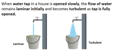
Reynolds Number: Reynolds Number is the ratio of Inertial forces to the Viscous forces. By knowing this number, one can describe the flow whether the flow is laminar, turbulent or transitional flow. There are three possibilities of the range of Reynolds Number: If Reynolds number < 2100 or 2300 ⟺ Laminar Flow If Reynolds number > 4000 ⟺ Turbulent Flow If 2300 < Reynolds number < 4000 ⟺ Transitional Flow In case of different shapes other than circle, the formula for Reynolds Number remain the same however diameter involves in the formula become Hydraulic Diameter which is given by: For pipe: Critical Reynolds Number ⟾ The Reynolds number at which the flow becomes turbulent Re cr For different shapes, the hydraulic diameters are given by: Completely Filled Flow In Closed Channel: If pipe is is considered to filled completely with closed channel, then following are the conditions which...
Intersection Of Solids: Solids are obtained by the combination of of two or more basic solids. When two or more solids combine, a definite curve/line is seen at their intersection. This curve/line is called curve/line of intersection (COI / LOI) and it is the result of inter-penetration of solids. Applications Of Intersection Of Solids: Designing a sheet metal objects. Automobile Parts. Moulding patterns. Forged end of connecting road. Intersection of two contacting surface, etc. Inter-Penetration Of Solids: When one solids penetrates another solids then their surfaces intersect and at the junction of intersection a typical curve is formed, which remains common to both solids. This curve is called Curve of Intersection and it is a result of inter-penetration of solids. Cases Of Intersection Of Solids: First we need to discuss the general solution steps of how we draw intersection of solids diagram. So know, we are going to discuss the basic steps:...
Types Of Lines And Its Uses: There are three types of types on the basis of thickness and they are: Visible Lines ↝ It represents features that can be seen in the current view. Hidden Lines ↝ It represents features that cannot be seen in the current view. Center Line ↝ It represents symmetry, path of motion, centers of circles,, axis of asymmetrical parts. Dimension and Extension Lines ↝ It indicates the sizes and location of features on a drawing. Placement Of Dimension Lines: Dimension should be outside the view. Dimension should be applied to one view. Dimension should be placed in a view that shows the distance in its true length. Dimension lines should be placed, in general 10 mm (1/2 in) away from the outlines from the view. Parallel lines should be placed uniformly. Values should be midway (auto centered) between the arrow heads, except when a center-line interferes. Dime...




Comments
Post a Comment
Questions or corrections are welcome. Please mention the relevant section and units. Do not post confidential project data or personal contact details. For project inquiries, use the Fluxiss contact page.