Every nozzle cut into a pressure vessel shell removes metal that was carrying load. ASME VIII Div. 1 handles this with the area replacement method: the metal removed must be put back within defined limits around the opening. This post walks through the method, explains when to use a reinforcing pad, a thicker neck or an insert plate, and works through a complete NPS 6 nozzle example. It builds on our wider guide to pressure vessel and storage tank design . Why an Opening Weakens a Shell A circular hole in a cylindrical shell under internal pressure creates a stress concentration. The peak stress at the edge of a plain hole is roughly 2.5 times the nominal hoop stress, and the hole interrupts exactly the metal that resists hoop stress. For a refresher on how a stress state resolves on different planes, see our note on stress transformation . The Code does not calculate the peak. It requires the removed metal to be replaced close to the opening, which keeps local stresses within the r...
Get link
Facebook
X
Pinterest
Email
Other Apps
Pipe Supports in Process Piping: Rests, Guides, Anchors and Spacing Under ASME B31.3
Get link
Facebook
X
Pinterest
Email
Other Apps
-
Pipe supports do more than hold weight. They decide where a line can move, where it cannot, and what loads reach racks, steel and equipment nozzles. Under ASME B31.3, support design is part of the flexibility and stress picture, not a separate drafting task. This post explains the main support types, how to check spans and thermal growth, and the practical checks that prevent problems in service.
Support Functions and Types
B31.3 Part 5 (paragraph 321) requires supports to carry the piping safely and to limit stresses and movements from weight, thermal expansion, wind, seismic and other loads. The code does not give a span table, so projects use their own standards, MSS SP-69 guidance or a calculation. Each support restrains specific directions:
Variable spring hangers are common where a line moves vertically, but the load they carry changes with travel. Projects often limit that variation to about 25%. Where movement is larger, or the line connects to sensitive equipment, constant effort supports keep the load almost steady.
Guides and line stops are often confused. A line stop restrains axial movement only, whereas a guide leaves the axial direction free. Anchors are the most expensive support in both loads and steel, so each one should have a reason that the stress analysis can show.
Span and Deflection Checks
For a first check, treat the pipe as a simply supported beam under uniform load w (pipe, contents, insulation and fittings, per metre):
Midspan deflection: δ = 5 w L⁴ / (384 E I)
Bending moment: M = w L² / 8, with stress σ = M / Z
Span for a given sag limit: L = [384 E I δ / (5 w)]1/4
Continuous spans are stiffer than simple ones, so the simple-beam result is conservative. Valves and other concentrated weights need extra supports nearby. Set a deflection limit in the project criteria. A few millimetres is common for liquid lines so they drain properly, while gas lines can tolerate more as long as condensate cannot pool. For ordinary spans, deflection governs well before the sustained stress limit (SL ≤ Sh) does.
Insulation, cladding and fluid density all change w, so recalculate when the service changes. Sloped lines that must drain, and thin-walled or large-diameter lines, may need shorter spans than the stress limit alone suggests.
Thermal Growth, Guides and Anchors
Thermal growth follows ΔL = α × L × ΔT. For carbon steel, α is about 12 × 10-6 per °C, though the expansion data in B31.3 Appendix C should be used in a formal analysis. Anchors divide a line into sections, and each section grows away from its anchor. Guides then direct that growth along the pipe axis and help prevent buckling.
Sliding supports transmit friction, F = μ × N, where N is the vertical load on the support. Steel on steel is often taken as μ = 0.3, and low-friction slide plates reduce it. This friction accumulates and loads the anchors. For lines with expansion joints, EJMA guidance places the first guide within about 4 pipe diameters of the joint and the second within about 14 diameters of the first.
At expansion joints and bellows, the unbalanced pressure thrust equals pressure times effective area, and the anchors or tie rods must carry it. This load is often larger than the friction or thermal forces.
A DN200 Schedule 40 carbon steel line (OD 219.1 mm, ID 202.7 mm) carries hot water at 150 °C. Take I = 3.02 × 10⁻⁵ m⁴, E = 200 GPa and a pipe weight of 42.5 kg/m. Use a water density of 1,000 kg/m³ for simplicity.
Step 1: Weight per metre. Water content = π/4 × 0.2027² × 1,000 = 32.3 kg/m. Total = 42.5 + 32.3 = 74.8 kg/m, so w = 74.8 × 9.81 ≈ 734 N/m.
Step 2: Allowable span. For a 5 mm sag limit, L = [384 × 200 × 109 × 3.02 × 10-5 × 0.005 / (5 × 734)]1/4 ≈ 7.5 m. Allowing for valves, fittings and a 6 m rack bent spacing, choose 6 m.
Step 3: Check the 6 m span. δ = 5 × 734 × 6⁴ / (384 × 6.04 × 106) ≈ 2.0 mm. Moment M = 734 × 36 / 8 ≈ 3.3 kN·m, and with Z = 2.76 × 10⁻⁴ m³, σ ≈ 12 MPa, far below the allowable. Deflection governs.
Step 4: Thermal growth. The line is 40 m between anchors, with an anchor at the middle, and ΔT = 150 − 20 = 130 °C. The full length would grow 12 × 10-6 × 40,000 × 130 = 62 mm, so each half grows about 31 mm away from the central anchor. Shoes and guides must allow that movement.
Step 5: Friction load. Each support carries 734 × 6 ≈ 4.4 kN, so sliding friction at μ = 0.3 is about 1.3 kN. Three supports on each side of the anchor add roughly 4 kN of axial load, before any pressure thrust or other loads.
If that friction load looks high for the anchor steel, low-friction slide plates, shorter thermal sections or an added expansion loop can reduce it.
Practical Engineering Checks
Load basis: include contents, insulation, valves and the hydrotest condition. Gas lines filled with water for testing often need temporary supports.
Movement and clearance: check thermal displacement at every support, including shoe length, guide gap and clearance to neighbouring steel.
Do not over-restrain: extra guides or stops can block growth and raise expansion stress and nozzle loads.
Spring hangers: confirm cold and hot loads, travel and load variation, and avoid rigid supports beside springs that could unload them.
Uplift and occasional loads: check wind, seismic and relief cases for lifted supports and for added restraint needs.
Local pipe stresses: trunnions, clamps and welded attachments create local stresses, and attachments must meet B31.3 requirements.
Corrosion: insulated pipe shoes and contact points can trap moisture, so specify protection.
Vibration: pump discharge and two-phase lines may need stiffer supports than static checks suggest.
Structure coordination: send support loads by case to the structural team, with updates after every revision.
Documentation: show support types and tags on stress isometrics, and keep the support schedule in step with the model.
How Fluxiss Delivers Support Design
Fluxiss is a multidisciplinary engineering consultancy. Its pipe stress analysis service selects support types and locations from the stress model, then passes the resulting support loads to structural design so racks and foundations can be checked against the same cases.
Frequently Asked Questions
Does ASME B31.3 give maximum support spacing?
No. The code sets the requirement that supports control stresses and movements, but it has no span table. Projects use their own standards, MSS SP-69 guidance or a calculation.
What is the difference between a guide and an anchor?
A guide limits lateral movement and allows axial sliding. An anchor restrains all movement and rotation, so it carries much larger loads.
Why not anchor every thermal section firmly?
Rigid anchors raise expansion stress and push large forces into steel and equipment. Use them only where the stress analysis shows they are needed.
When do I need spring hangers?
When a hot or cold line moves vertically enough that a rigid support would lift off or overload. Springs keep the support load within an acceptable range as the pipe moves.
Need help with pipe supports and stress analysis?
Fluxiss provides pipe stress analysis that covers support selection, spacing checks and support load schedules for oil and gas, power and industrial projects.
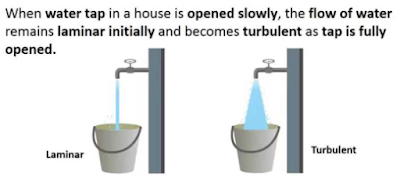
Reynolds Number: Reynolds Number is the ratio of Inertial forces to the Viscous forces. By knowing this number, one can describe the flow whether the flow is laminar, turbulent or transitional flow. There are three possibilities of the range of Reynolds Number: If Reynolds number < 2100 or 2300 ⟺ Laminar Flow If Reynolds number > 4000 ⟺ Turbulent Flow If 2300 < Reynolds number < 4000 ⟺ Transitional Flow In case of different shapes other than circle, the formula for Reynolds Number remain the same however diameter involves in the formula become Hydraulic Diameter which is given by: For pipe: Critical Reynolds Number ⟾ The Reynolds number at which the flow becomes turbulent Re cr For different shapes, the hydraulic diameters are given by: Completely Filled Flow In Closed Channel: If pipe is is considered to filled completely with closed channel, then following are the conditions which...
Intersection Of Solids: Solids are obtained by the combination of of two or more basic solids. When two or more solids combine, a definite curve/line is seen at their intersection. This curve/line is called curve/line of intersection (COI / LOI) and it is the result of inter-penetration of solids. Applications Of Intersection Of Solids: Designing a sheet metal objects. Automobile Parts. Moulding patterns. Forged end of connecting road. Intersection of two contacting surface, etc. Inter-Penetration Of Solids: When one solids penetrates another solids then their surfaces intersect and at the junction of intersection a typical curve is formed, which remains common to both solids. This curve is called Curve of Intersection and it is a result of inter-penetration of solids. Cases Of Intersection Of Solids: First we need to discuss the general solution steps of how we draw intersection of solids diagram. So know, we are going to discuss the basic steps:...
Types Of Lines And Its Uses: There are three types of types on the basis of thickness and they are: Visible Lines ↝ It represents features that can be seen in the current view. Hidden Lines ↝ It represents features that cannot be seen in the current view. Center Line ↝ It represents symmetry, path of motion, centers of circles,, axis of asymmetrical parts. Dimension and Extension Lines ↝ It indicates the sizes and location of features on a drawing. Placement Of Dimension Lines: Dimension should be outside the view. Dimension should be applied to one view. Dimension should be placed in a view that shows the distance in its true length. Dimension lines should be placed, in general 10 mm (1/2 in) away from the outlines from the view. Parallel lines should be placed uniformly. Values should be midway (auto centered) between the arrow heads, except when a center-line interferes. Dime...




Comments
Post a Comment
Questions or corrections are welcome. Please mention the relevant section and units. Do not post confidential project data or personal contact details. For project inquiries, use the Fluxiss contact page.