View Factor Orientation (or View factor or shape factor) plays an important role in radiation heat transfer. View factor is defined as, "fraction of radiation leaving surface 'i' and strike 'j' ". Summation Rule (View Factor) If there is are similar surfaces 'i' and 'j' , then: Blackbody Radiation Exchange Radiation Exchange between Opaque, Diffuse, Gray surfaces in an Enclosure 1. Opaque 2. Surfaces 3. Two surface enclosure Radiation Shield It is used to protect surfaces from radiation act like a reflective surface. References: Material from Class Lectures + Book named Fundamentals of Heat and Mass Transfer by Theodore L. Bergman + My knowledge. Photoshoped pics are developed. Some pics and GIF from Google. Videos from YouTube ( Engineering Sights ).
Get link
Facebook
X
Pinterest
Email
Other Apps
Piping Or Industrial Process Of Piping
Get link
Facebook
X
Pinterest
Email
Other Apps
-
Industrial Process Of Piping:
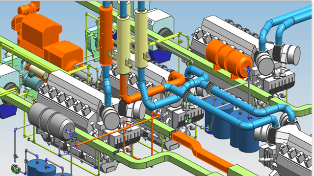
Industrial process of piping involves the usage of piping to transport fluids between storage tanks and processing equipment.
Types Of Piping:
Plumbing
Civil Piping
Transportation Piping
Uses Of Industrial Piping:
Water
Natural Gas
Electric Power
Specially items like paper pulp or liquid foods
Sewer
Storm drains, etc.
Pipe Drafting:
Pipe can be drawn into two forms Double-line & Single-line. Pipe drafting utilizes many different types of drawings:
Flow Diagrams
Structural and Site plans
Mechanical and Instrumentation Drawings
Iso-Symbols Of Fittings:
It is a mechanical tool which is used to join two or more components together.
Iso-Symbols Of Flanges:
A flange is a method of connecting pipes, valves, pumps and other equipment to form a piping system.
Iso-Symbols Of Valves:
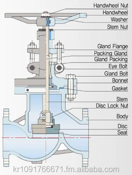
A valve is a device that regulates the flow of fluids, fluidised solids, slurries or liquid, by opening, closing, or partially obstructing various passageways.
Isometric Drawing Offsets:
Hatches on isometric drawings being applied, to indicate that a pipe runs at a certain angle and in which direction the pipe runs.
There are two types of offsets:
Horizontal Offset
Vertical Offset
Types Of Valves :
Following are the types of valves used in Mechanical Engineering:
1. Gate Valves:
A gate valve is a linear motion valve used to start or stop fluid flow. It doesn't regulate or throttle flow.
2. Globe Valve:
A globe valve is linear motion valve used to stop, start, regulate flow of fluid.
3. Butterfly Valve:
A butterfly valve is a rotary motion valve that is used to start, stop, and regulate fluid flow. It can be easily and quickly operated because a 90-degree rotation of the handle moves the disk from a fully closed to fully opened position.
4. Check Valve:
Check valve are designed to prevent the reversal of flow in a piping system. These valves are activated by the flow materials in the pipeline.
You should provide video tutorials for Engineering Drawing for the better visualization. That's just to make you realize Engineering is visualization not theoretical. Hope you understand this������
Mechanical Injection System: Used to inject fuel into the combustion chamber. Fuel speed > air speed at delivery point to atomize fuel. Amount of fuel delivered into the air stream going into the engine is controlled by pump which forces the fuel under pressure. A device used to initiate and control the combustion process is called Mechanical Injection System. Functional Requirements of Injection System: Metering of Fuel: Used to control fuel to meet speed and load requirements of the engine. Injection Timing: Have proper injection timing to obtain max. power, fuel economy and proper burning. It is done by Camshaft or Push rod (Rocker Arm) Mechanism . Proper Control of Injection Rate: To get desired heat release pattern during combustion. Proper Atomization of Fuel: Proper making of droplets to make best Air/Fuel mixture. Proper Spray Pattern: Distribution of droplets to ensure rapid mixing of fuel & air. Uniform Distribut...
Projection: The term Projection is defined as: Presentation of an image or an object on a surface. The principles used to graphically represent 3-D objects and structures on 2-D media and it based on two variables: Line of Sight. Plane of Projection. Line of Sight & Plane of Projection: Line of sight is divided into 2 types: Parallel Projection Converging Projection & A plane of projection is an imaginary flat plane upon which the image created by the lines of sight is projected. Orthographic Projection: When the projectors are parallel to each other and perpendicular to the plane of projection. The lines pf sight of the observer create a view on the screen. The screen is referred to as the Plane of Projection (POP). The lines of sight are called Projection lines or projectors. Rules of Orthographic Projection: Edges that are parallel to a plane of projection appear as lines. Edges that are incl...
Gear Forming by Machining Formation of gear through machining consists of following methods: Form Milling by Disc Cutter Form Milling by End Mill Cutter Shaper, Planner and Slotter Broaching 1. Form Milling by Disc Cutter It is defined as, " Tooth is cut one by one by plunging the rotating cutter into the blank " . Each gear needs a separate cutter. 8 - 10 standard cutters are available for producing 12 - 120 teeth gears. Used for big spur gears of large pitch. 2. Form Milling by End Mill Cutter It includes the cutting of tooth at a time and then indexed for the next tooth space for cutting. For a small volume production of low precision gears. Set of 10 cutters ↠ 12 - 120 teeth gears . Used for teeth of large gears/module. To reduce cost, same cutter is often used for multiple sized gears resulting in profile errors . Characteristics: Use of Hardened stainless steels (HSS) form milling cutters. Use of Ordinary milling machines. Low production rate (need of indexing...





You should provide video tutorials for Engineering Drawing for the better visualization. That's just to make you realize Engineering is visualization not theoretical. Hope you understand this������
ReplyDelete