View Factor Orientation (or View factor or shape factor) plays an important role in radiation heat transfer. View factor is defined as, "fraction of radiation leaving surface 'i' and strike 'j' ". Summation Rule (View Factor) If there is are similar surfaces 'i' and 'j' , then: Blackbody Radiation Exchange Radiation Exchange between Opaque, Diffuse, Gray surfaces in an Enclosure 1. Opaque 2. Surfaces 3. Two surface enclosure Radiation Shield It is used to protect surfaces from radiation act like a reflective surface. References: Material from Class Lectures + Book named Fundamentals of Heat and Mass Transfer by Theodore L. Bergman + My knowledge. Photoshoped pics are developed. Some pics and GIF from Google. Videos from YouTube ( Engineering Sights ).
Get link
Facebook
X
Pinterest
Email
Other Apps
Piping Or Industrial Process Of Piping
Get link
Facebook
X
Pinterest
Email
Other Apps
-
Industrial Process Of Piping:
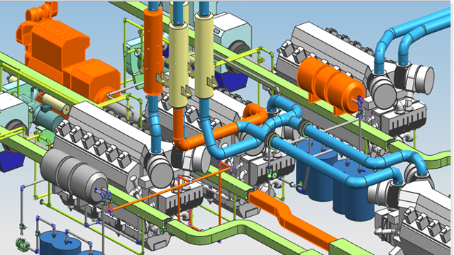
Industrial process of piping involves the usage of piping to transport fluids between storage tanks and processing equipment.
Types Of Piping:
Plumbing
Civil Piping
Transportation Piping
Uses Of Industrial Piping:
Water
Natural Gas
Electric Power
Specially items like paper pulp or liquid foods
Sewer
Storm drains, etc.
Pipe Drafting:
Pipe can be drawn into two forms Double-line & Single-line. Pipe drafting utilizes many different types of drawings:
Flow Diagrams
Structural and Site plans
Mechanical and Instrumentation Drawings
Iso-Symbols Of Fittings:
It is a mechanical tool which is used to join two or more components together.
Iso-Symbols Of Flanges:
A flange is a method of connecting pipes, valves, pumps and other equipment to form a piping system.
Iso-Symbols Of Valves:
A valve is a device that regulates the flow of fluids, fluidised solids, slurries or liquid, by opening, closing, or partially obstructing various passageways.
Isometric Drawing Offsets:
Hatches on isometric drawings being applied, to indicate that a pipe runs at a certain angle and in which direction the pipe runs.
There are two types of offsets:
Horizontal Offset
Vertical Offset
Types Of Valves :
Following are the types of valves used in Mechanical Engineering:
1. Gate Valves:
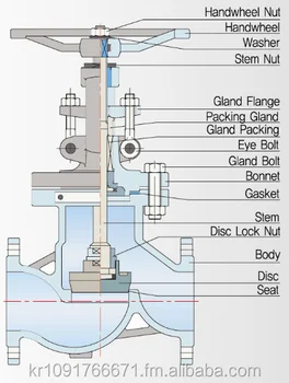
A gate valve is a linear motion valve used to start or stop fluid flow. It doesn't regulate or throttle flow.
2. Globe Valve:
A globe valve is linear motion valve used to stop, start, regulate flow of fluid.
3. Butterfly Valve:
A butterfly valve is a rotary motion valve that is used to start, stop, and regulate fluid flow. It can be easily and quickly operated because a 90-degree rotation of the handle moves the disk from a fully closed to fully opened position.
4. Check Valve:
Check valve are designed to prevent the reversal of flow in a piping system. These valves are activated by the flow materials in the pipeline.
You should provide video tutorials for Engineering Drawing for the better visualization. That's just to make you realize Engineering is visualization not theoretical. Hope you understand this������
Solid Mechanics OR Mechanics of Materials OR Strength of Materials: It is the study of mechanics of body i.e. forces and their effects on deformable solids under different loading conditions. Deformable Body Mechanics: It is the study of non-rigid solid structures which deform under load. Deformation/Distortion ⇾ change of shape and size OR have some relative displacement or rotation of particles. It happens when we apply combined load. Rigid Body Motion ⇾ Translation or rotation of particles but having constant distance between particles. Since deformation occur at particular load. Below this load, every body is considered as rigid body . Types of Load: Point Load ⇾ Load apply on a single point i.e. concentrated load. Uniformly Distributed Load (UDL) ⇾ Load remains uniform throughout an area of element like beam. Varying Distributed Load (VDL) ⇾ Load varies with length with constant rate. Moment ⇾ It measures the tend...
Introduction To Structural OR Concrete Design Beams must have adequate strength against different types of failure which are: Shear more dangerous than Flexural (or Bending) failure because it creates additional tensile stresses. E.g.: Airplane wing (act as cantilever beam ) and made of Nanocomposites, composites, aluminum. Following are the types of failures in Beam: Flexural (or bending) failure Diagonal Tension failure Shear-Tension failure Shear-Compression failure Following are the types of Shear : Longitudinal Shear Transverse Shear Shear Failure Diagonal Tension Failure ↠ Shear failure of reinforced concrete beam (difficult to predict). Only valid for Homogenous beams . When we apply load on beam ↠ Bending as well as Shear stresses are produced. Shear stress have maximum value at Neutral axis N.A. Bending stress have maximum value at Extreme fibers. At maximum bending stress ↠ shear stress = 0 . Assumptions for shear stresses i...
Mechanical Injection System: Used to inject fuel into the combustion chamber. Fuel speed > air speed at delivery point to atomize fuel. Amount of fuel delivered into the air stream going into the engine is controlled by pump which forces the fuel under pressure. A device used to initiate and control the combustion process is called Mechanical Injection System. Functional Requirements of Injection System: Metering of Fuel: Used to control fuel to meet speed and load requirements of the engine. Injection Timing: Have proper injection timing to obtain max. power, fuel economy and proper burning. It is done by Camshaft or Push rod (Rocker Arm) Mechanism . Proper Control of Injection Rate: To get desired heat release pattern during combustion. Proper Atomization of Fuel: Proper making of droplets to make best Air/Fuel mixture. Proper Spray Pattern: Distribution of droplets to ensure rapid mixing of fuel & air. Uniform Distribut...





You should provide video tutorials for Engineering Drawing for the better visualization. That's just to make you realize Engineering is visualization not theoretical. Hope you understand this������
ReplyDelete