Wind often governs lateral design and roof uplift on steel industrial buildings, yet the ASCE 7 procedure is easy to misapply when editions mix. This post answers three common questions, then works an example for a steel-frame building. It extends our overview of structural engineering for industrial plants . Steel-frame building under construction. Photo: Dwight Burdette, CC BY 3.0, via Wikimedia Commons . What is the formula for calculating wind load? For a building, the design wind pressure on a surface is p = q G Cp − qi (GCpi), and the force is F = p × A, where A is the tributary area. The velocity pressure follows from wind velocity: qz = 0.00256 Kz Kzt Kd Ke V² in psf with V in mph, or qz = 0.613 Kz Kzt Kd Ke V² in N/m² with V in m/s. Kz is the height exposure coefficient, Kzt the topographic factor, Kd the wind directionality factor, Ke the ground elevation factor (ASCE 7-16 onward), G the gust factor (0.85 for rigid buildings) and Cp the external pressure coefficient. Th...
Get link
Facebook
X
Pinterest
Email
Other Apps
Pipe Pressure Drop Calculation: Darcy-Weisbach, Friction Factor and Pipe Sizing Worked Example
Get link
Facebook
X
Pinterest
Email
Other Apps
-
Pressure drop decides pump head, compressor discharge pressure, fan power and how far a line can run, so it is one of the most frequent calculations in piping design. This post answers the four questions engineers search for most, then works through a water line in Sch 40 steel pipe in SI units with US equivalents. It builds on our post on internal flows.
Work through the same steps for any pipe flow: fix the flow rate and fluid properties, find the velocity, find the Reynolds number Re = ρ v D / μ, get the friction factor f, then apply the Darcy–Weisbach equation to the straight pipe and add the minor losses for pipe fittings and valves. Add the static pressure change from elevation, ρ g Δz, to get the total. The friction factor comes from the Moody chart or, more conveniently, from an explicit fit such as Swamee–Jain, so the whole pipe flow calculation runs in an Excel sheet or a calculator without iteration.
The method also serves compressed air pressure checks and air pipe sizing, with care: gas density changes with pressure, so use the density at the average pressure, or the isothermal gas equations when the drop exceeds about 10% of the inlet pressure. In compressed air piping systems the allowable drop is usually a small fraction of the supply pressure, set by the project specification. Friction loss in the pipe is the main term for long runs, and fittings dominate short, congested ones.
How much pressure drop per 100 ft of pipe?
There is no single value, because it depends on flow, diameter, roughness and fluid. Water designs commonly aim for about 1 to 4 ft of head per 100 ft, roughly 0.4 to 1.7 psi per 100 ft, to balance pipe cost and pumping energy; our chilled water pipe sizing post works in 100 to 400 Pa/m. In the worked example below, 220 gpm through 4 inch Sch 40 steel pipe loses 1.17 psi per 100 ft. Material changes the result through roughness and inside diameter: for the same inside diameter, smooth copper tubing or PEX gives a friction factor about 15% lower than steel here, but corrugated hose and flexible connectors lose far more, so take their drop from the manufacturer's data. Use a size chart for a first pass and the calculation for the final check; for compressed air pipe sizing, charts list the drop per length against flow and pressure.
What is the pressure drop formula?
The core formula is the Darcy–Weisbach equation, with the related relations below:
Darcy–Weisbach: Δp = f (L/D) ρ v² / 2, or head loss hf = f (L/D) v² / (2g)
Laminar flow (Re < 2,300): f = 64 / Re, equivalent to Δp = 32 μ L v / D²
Minor losses: Δp = K ρ v² / 2, or equivalent length Le = K D / f
Control valve: Δp = SG (Q / Kv)², with Q in m³/h and Δp in bar
The Darcy–Weisbach equation applies to water, oil and gas pipe flow alike, and to duct pressure with the hydraulic diameter in place of D. The minor-loss form covers any valve or louvre when a K value is known, and heat exchanger pressure drop is usually taken from selection data because it also includes the effect of the heat transfer surface. Two-phase flow has no single formula and needs methods such as Lockhart–Martinelli or specialised software, and high-velocity gas lines need the compressible flow equations.
Measure it across the component with a gauge or a differential pressure transmitter, with taps upstream and downstream, and compare with the calculated value at the same flow. In HVAC the same idea gives static pressure readings across an air filter, an evaporator coil or the air handler; a rising filter drop signals loading, and the coil and filter drops should match their data sheets at the measured airflow. A check valve has a cracking pressure, the minimum differential that opens it, so confirm it against the flow range. For a control valve, check the drop at design flow against the sizing calculation, and keep a reasonable share of the circuit drop across it so it controls. On pumps, high suction drop cuts NPSH available, as in our NPSH available calculation post, and rapid valve closure adds a transient surge, covered in our water hammer calculation guide.
Worked Example: Water in 4 Inch Sch 40 Pipe
Water at 20 °C (ρ = 998 kg/m³, μ = 1.002 mPa·s) flows at 50 m³/h (220 gpm) through 150 m (492 ft) of DN100 (NPS 4) Sch 40 steel pipe, with an inside diameter of 102.3 mm and roughness ε = 0.046 mm. The line has 6 elbows (K = 0.30 each), 2 gate valves (K = 0.15 each), a check valve (K = 2.0) and a strainer (K = 1.5), so ΣK = 5.6.
Step
Calculation (SI)
Result (US)
Velocity
0.01389 / (π/4 × 0.1023²)
1.69 m/s (5.54 ft/s)
Reynolds number
998 × 1.69 × 0.1023 / 0.001002
172,000
Friction factor
Swamee–Jain, ε/D = 4.50 × 10⁻⁴
f = 0.0189
Dynamic pressure
998 × 1.69² / 2
1.425 kPa
Straight pipe
0.0189 × (150 / 0.1023) × 1,425
39.6 kPa (5.74 psi)
Fittings
5.6 × 1,425
8.0 kPa (1.16 psi)
Total friction loss
39.6 + 8.0
47.6 kPa (6.90 psi), 4.86 m (15.9 ft) of water
Per 100 ft
39.6 × 30.48 / 150
8.0 kPa (1.17 psi)
The total friction loss is 47.6 kPa, with the straight pipe contributing 83% and the fittings 17%. Elevation adds separately: a 6 m rise adds ρ g Δz = 58.7 kPa, so a pump would need about 106 kPa of differential before any control valve or equipment drop. The velocity of 1.69 m/s sits in a normal range for water, and 1.17 psi per 100 ft is within the usual guidance. If a smaller DN80 pipe were used, the velocity would rise to about 2.9 m/s and the friction loss by roughly a factor of four, which shows why diameter dominates.
Practical Checks
Roughness: add an allowance for ageing, because corrosion and scale raise friction over time.
Viscosity: use the value at operating temperature, which matters for oil and glycol.
Velocity limits: keep velocity within noise, erosion and surge guidance as well as pressure drop.
Fittings: use K values for the actual fitting and size, and manufacturer data for strainers and check valves.
Worst case: evaluate at maximum flow and with a dirty strainer or filter.
Documentation: keep the spreadsheet with inputs, formulas and sources, and hand-check one case.
Stress interface: the pressure profile along the line feeds the pressure design and the stress analysis.
How Fluxiss Approaches Pressure Drop
Fluxiss is a multidisciplinary engineering consultancy serving oil and gas, power and maritime clients. Its piping team checks line sizing and pressure drop together with layout, supports and stress analysis, so the hydraulic basis and the mechanical design agree.
Frequently Asked Questions
Which friction factor equation should I use?
Colebrook is the reference, and Swamee–Jain is explicit and close enough for design. Moody chart readings agree with both.
Is pressure drop the same as head loss?
They are related by Δp = ρ g h. Use head for liquids on pump curves, and pressure for gases and equipment.
Do fittings matter in long lines?
Little in very long runs, but they dominate short, congested lines such as pump stations.
When is Darcy–Weisbach not enough?
For two-phase flow, high-velocity gas and non-Newtonian fluids, which need specialised methods.
Need help with line sizing and pipe stress analysis?
Fluxiss provides piping and stress analysis for process, power and marine piping, including line sizing, pressure drop and support design. Send your line list and layout, and the team can advise on the checks you need.
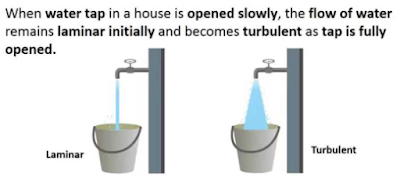
Reynolds Number: Reynolds Number is the ratio of Inertial forces to the Viscous forces. By knowing this number, one can describe the flow whether the flow is laminar, turbulent or transitional flow. There are three possibilities of the range of Reynolds Number: If Reynolds number < 2100 or 2300 ⟺ Laminar Flow If Reynolds number > 4000 ⟺ Turbulent Flow If 2300 < Reynolds number < 4000 ⟺ Transitional Flow In case of different shapes other than circle, the formula for Reynolds Number remain the same however diameter involves in the formula become Hydraulic Diameter which is given by: For pipe: Critical Reynolds Number ⟾ The Reynolds number at which the flow becomes turbulent Re cr For different shapes, the hydraulic diameters are given by: Completely Filled Flow In Closed Channel: If pipe is is considered to filled completely with closed channel, then following are the conditions which...
Heat exchangers move thermal energy from one fluid to another without letting the fluids mix. They sit in nearly every process, power and utility system, from crude preheat trains to lube oil coolers. Getting one right means getting the thermal duty, the pressure drop and the mechanical design right together. This post covers the fundamentals, the key equations, a worked sizing example and the checks engineers apply before releasing a design. Tube bundle of a shell-and-tube heat exchanger. Photo by Alnitak3/Wikimedia Commons , licensed CC BY-SA 4.0 . Heat Exchanger Fundamentals Heat flows from the hot stream through a wall to the cold stream. Three resistances act in series: convection on the hot side, conduction through the tube or plate wall, and convection on the cold side. Fouling layers add resistance on each surface over time. The designer's job is to provide enough surface area to transfer the required duty with acceptable pressure drop and cost. Type Strengths Limits...
Intersection Of Solids: Solids are obtained by the combination of of two or more basic solids. When two or more solids combine, a definite curve/line is seen at their intersection. This curve/line is called curve/line of intersection (COI / LOI) and it is the result of inter-penetration of solids. Applications Of Intersection Of Solids: Designing a sheet metal objects. Automobile Parts. Moulding patterns. Forged end of connecting road. Intersection of two contacting surface, etc. Inter-Penetration Of Solids: When one solids penetrates another solids then their surfaces intersect and at the junction of intersection a typical curve is formed, which remains common to both solids. This curve is called Curve of Intersection and it is a result of inter-penetration of solids. Cases Of Intersection Of Solids: First we need to discuss the general solution steps of how we draw intersection of solids diagram. So know, we are going to discuss the basic steps:...




Comments
Post a Comment
Questions or corrections are welcome. Please mention the relevant section and units. Do not post confidential project data or personal contact details. For project inquiries, use the Fluxiss contact page.