View Factor Orientation (or View factor or shape factor) plays an important role in radiation heat transfer. View factor is defined as, "fraction of radiation leaving surface 'i' and strike 'j' ". Summation Rule (View Factor) If there is are similar surfaces 'i' and 'j' , then: Blackbody Radiation Exchange Radiation Exchange between Opaque, Diffuse, Gray surfaces in an Enclosure 1. Opaque 2. Surfaces 3. Two surface enclosure Radiation Shield It is used to protect surfaces from radiation act like a reflective surface. References: Material from Class Lectures + Book named Fundamentals of Heat and Mass Transfer by Theodore L. Bergman + My knowledge. Photoshoped pics are developed. Some pics and GIF from Google. Videos from YouTube ( Engineering Sights ).
Get link
Facebook
X
Pinterest
Email
Other Apps
Isometric Projection Of Solids
Get link
Facebook
X
Pinterest
Email
Other Apps
-
Isometric Drawing:
A type of pictorial projection in which all three dimensions of an object are shown in one view.
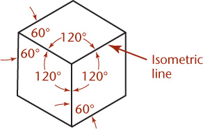
In this 3-D drawing of an object, all three dimensional axes are maintained at equal inclinations with each other , i.e. 120 degrees.
All mutual perpendicular plane surfaces of an object and the edges formed by these surfaces are equally inclined to POP.
When orthographic views are given, a good imagination is needed to visualize the object in 3-D space.
Some Important Terms:
The angle between these axes are equal i.e. 120 degrees, so called Isometric Axes.
The line parallel to these axes are called Isometric Lines.
The planes representing the cube are called Isometric Planes.
The reduction is approximately 0.815. It forms a reducing scale which is used to draw isometric projection and is called Isometric Scale.
True-length Distances are shown along isometric lines.
Isometric line is the line that run parallel to any of the isometric axes.
Types Of Isometric Drawings:
There are two types of isometric drawing, namely:
Isometric Projections.
Isometric Views.
1. Isometric Projections:
All the edges of the cube are equally inclined to the plane of projection, they get equally foreshortened in isometric projection.
2. Isometric Views:
It is way by which you can represent your shapes into 3-D view.
Isometric Of Plane Figures:
For 2-D figures only two isometric axes are required.
Shape containing inclined lines should be enclosed in a rectangle
Draw isometric of the rectangle and then inscribe that shape in it.
Example of Isometric Projection:
How we convert orthographic views into isometric projection is completely described by the video given below:
Projection: The term Projection is defined as: Presentation of an image or an object on a surface. The principles used to graphically represent 3-D objects and structures on 2-D media and it based on two variables: Line of Sight. Plane of Projection. Line of Sight & Plane of Projection: Line of sight is divided into 2 types: Parallel Projection Converging Projection & A plane of projection is an imaginary flat plane upon which the image created by the lines of sight is projected. Orthographic Projection: When the projectors are parallel to each other and perpendicular to the plane of projection. The lines pf sight of the observer create a view on the screen. The screen is referred to as the Plane of Projection (POP). The lines of sight are called Projection lines or projectors. Rules of Orthographic Projection: Edges that are parallel to a plane of projection appear as lines. Edges that are incl...
Flywheel It is defined as, " a machine element which serves as reservoir which stores energy during the period when energy supply is more than the requirement and releases it when energy is less than requirement " . Used in IC, reciprocating (compressors or pumps) engines, presses, etc. Excess energy is stored in flywheel and release to crankshaft during other strokes in which no energy is developed. If space is small ↠ use small diameter and solid flywheel . If space is not limited (like for presses, crushing machine, hammering machine) ↠ use large diameter and hollow flywheel . Purpose of flywheel is to: reduce amplitude of speed fluctuation (sinusoidal) for constant power output. reduce maximum torque required. energy stored and release when needed during cycle. Parts of flywheel are Rim ↠ outer portion of flywheel (which is like a wheel). Hub ↠ center part which is installed on shaft. Arms or Needle ↠ rods joining rim to ...
Angles & Directions Angles are also called bearings. Bearings are the acute angles between lines and meridians. They are divided into following types. Related Terms : Meridian : Imaginary line joining North and South poles. Declination : Difference between magnetic and true meridians. Azimuth : Clockwise angle taken from Geodatic North. * If area is greater ➤ use Geodatic North * If area is smaller ➤ use Magnetic North Magnetic Declination maybe towards East or West. For east ➤ Magnetic bearing=true bearing - Declination For west ➤ Magnetic bearing=true bearing + Declination Forward Bearing : Bearing taken in the direction of traverse. Backward Bearing : Bearing taken in opposite direction of traverse. Forward bearing - Backward bearing=180 For anti-clockwise : FB of line = BB of previous line + angle Example: In an anti-clockwise traverse <A=102'30',...


Comments
Post a Comment
HI, we wI'll contact you later