An airfoil is the cross-section of a wing, blade, rudder or foil, shaped to produce lift with as little drag as possible. The same theory applies in air and in water, from aircraft wings and wind turbine blades to ship rudders, keels and hydrofoils. This post covers the fundamentals, the key equations, a worked wing example and the checks that keep airfoil estimates useful in design. Aircraft model in the NASA Ames 40x80 ft wind tunnel. Photo: NASA Ames Research Center / NASA , Public domain via Wikimedia Commons Airfoil Fundamentals A flowing fluid creates lift on an airfoil because the pressure on the lower surface is higher than on the upper surface. Equivalently, the airfoil generates circulation around itself. The sharp trailing edge fixes the flow there (the Kutta condition), which sets the amount of circulation and therefore the lift. Term Meaning Chord (c) Straight-line distance from leading edge to trailing edge Camber Curvature of the mean line, which gives lift at ...
Get link
Facebook
X
Pinterest
Email
Other Apps
Marine Engineering and Naval Architecture: Stability, Loads and Design Workflow
Get link
Facebook
X
Pinterest
Email
Other Apps
-
A vessel or floating structure has to float upright, move through water efficiently, survive the sea and satisfy a class society before it can sail. Each of those requirements is a naval architecture problem, and they interact. This post explains the core calculations and the design workflow behind marine engineering and naval architecture services, from stability to class approval.
Underwater hull form of the SS Great Britain in dry dock. Photo: Nortix08, CC BY-SA 4.0 via Wikimedia Commons
Intact Stability and GM
Intact stability describes a vessel's ability to return upright after a heel disturbance. The starting measure is the metacentric height, GM = KM − KG, where KM = KB + BM and BM = I / ∇ (waterplane second moment of area divided by displaced volume). The GZ curve then shows the righting lever across all heel angles. Its shape matters more than GM alone.
Worked example. A box barge is 40 m long, 10 m wide, floats at a 2 m draft and has KG = 3.0 m.
Displaced volume ∇ = 40 × 10 × 2 = 800 m³.
KB = T / 2 = 1.0 m.
I = L × B³ / 12 = 40 × 1,000 / 12 = 3,333 m⁴, so BM = 3,333 / 800 = 4.17 m.
KM = 1.0 + 4.17 = 5.17 m, so GM = 5.17 − 3.0 = 2.17 m.
Real vessels also need a free surface correction for slack tanks, which reduces effective GM. The IMO Intact Stability (IS) Code sets minimum criteria for many vessel types:
Criterion
Typical IS Code minimum
Initial metacentric height
GM ≥ 0.15 m
Area under GZ curve to 30°
≥ 0.055 m·rad
Area under GZ curve to 40° (or flooding angle)
≥ 0.09 m·rad
Area between 30° and 40°
≥ 0.03 m·rad
Righting lever
GZ ≥ 0.20 m at 30° or more, with maximum GZ at not less than 25°
A weather criterion also checks the vessel against severe wind and rolling. Some vessel types have additional or different requirements from class or flag rules, so confirm the governing criteria before the first loading condition is run.
Damage Stability
Damage stability asks whether the vessel survives flooding after a hull breach. Passenger and many cargo ships are assessed under SOLAS using a probabilistic method, where an attained subdivision index must meet or exceed a required index. Other vessel types, such as oil tankers, offshore vessels and special-purpose ships, are assessed using deterministic damage cases set by the applicable rules. The work needs a watertight subdivision model, permeabilities, openings and downflooding points. The output is a set of approved loading conditions and operating limits, usually in the stability booklet.
Weight Control and Lightship
Every stability and powering result depends on weight and centre of gravity. Build a weight estimate early, keep it in a controlled database with longitudinal, vertical and transverse centres, and carry design and growth margins appropriate to the project phase. Weights typically creep upward during detail design and construction, so review the estimate against the latest drawings at each milestone.
The lightship weight and VCG are confirmed at the end of construction by an inclining experiment, following the IS Code procedure. The measured values replace the estimate in all loading calculations. A poor weight estimate can mean late ballast, reduced payload or failed stability criteria, so treat it as a core deliverable.
Hydrostatics, Resistance and Powering
Hydrostatic tables give displacement, KB, BM, centre of buoyancy, tonnes per centimetre immersion and moment to change trim at each draft. They feed the loading and trim calculations.
Resistance has frictional, residuary, appendage and air components. Early estimates often use the ITTC-1957 friction line with empirical methods such as Holtrop-Mennen, and final results come from model tests or CFD. Effective power is resistance times speed. Dividing by the propulsive efficiency gives delivered power, and adding shaft losses and a sea margin, commonly 10–20% depending on route and weather, gives the required brake power. Energy efficiency rules such as EEDI and EEXI increasingly limit the installed power, so the powering estimate affects regulatory compliance as well as cost.
Hull Structure and Class Rules
Class societies such as DNV, ABS and Lloyd's Register publish rules for hull scantlings, materials, welding and equipment. For bulk carriers and oil tankers, the IACS Common Structural Rules apply. The structural design usually proceeds in this order:
Design loads: hydrostatic pressure, wave loads, cargo and ballast loads, and inertial loads.
Hull girder strength: still-water plus wave bending moments set the required midship section modulus.
Local scantlings: plating, stiffeners and girders sized to the rule pressures, with net-thickness corrosion margins.
Direct strength analysis: finite element models of cargo holds and critical areas, including buckling and fatigue checks.
Material grades: chosen by location, thickness and design temperature.
Early dialogue with the class surveyor on novel arrangements or unusual loads avoids rework at the approval stage.
Seakeeping and Mooring
Seakeeping analysis predicts vessel motions in waves using response amplitude operators for heave, pitch and roll. Results are checked against criteria for accelerations, deck wetness, slamming and operability, and for floating cargo or crane vessels they set weather limits. Barge transport and towing studies use the same motion data to size sea-fastening and tie-down loads.
Mooring analysis starts from wind, current and wave loads on the vessel. Line and fender selection follows industry guidance such as OCIMF for terminals, and DNV or API RP 2SK for offshore stationkeeping. Check line breaking loads against the required safety factors, and examine dynamic effects where wave loads are significant.
Engine room of the steamship Virginia V. Photo: Joe Mabel, CC BY-SA 4.0 via Wikimedia Commons
Marine Piping and Machinery Systems
Ships and offshore units depend on compact, class-approved systems:
Fluid systems: ballast, bilge, fuel oil, lube oil, cooling water, fire fighting, fresh water and compressed air.
Piping classes: class rules grade pipes by pressure, temperature and fluid, which sets material, thickness and testing.
Flexibility: account for thermal growth and hull deflection, which are major drivers on long runs through tanks and engine rooms.
Machinery: engine room arrangement, shaft alignment, vibration, exhaust and ventilation.
Pumps: size to the duty point and check NPSH, especially for suction lines with long runs.
Design Workflow and Class Approval Deliverables
Define owner requirements, operating profile and applicable rules.
Develop the general arrangement, lines plan and tank layout.
Prepare the weight estimate and run hydrostatics and intact stability.
Estimate resistance and powering, then select machinery.
Design the hull structure and submit approval drawings to class.
Complete damage stability, systems design and detailed drawings.
Prepare the stability booklet, then update after the inclining experiment.
Typical class submissions include the general arrangement, capacity plan, lines plan, midship section, shell expansion, structural drawings, stability calculations, piping diagrams, machinery arrangement and electrical single-line diagrams.
How Fluxiss Delivers Marine Engineering
Fluxiss is a multidisciplinary engineering consultancy that serves maritime clients alongside oil and gas and power. The naval architecture and marine engineering service supports stability, structural and systems work, and coordinates with piping and structural engineering teams where marine projects need them.
Frequently Asked Questions
What is the difference between intact and damage stability?
Intact stability covers an undamaged vessel under heel, wind and loading. Damage stability checks whether it stays afloat and upright after flooding from a hull breach. Both are required, and the rules depend on vessel type.
Why is an inclining experiment needed?
Estimated lightship weight and centre of gravity contain errors. The experiment measures the real values, which then replace the estimates in all loading and stability calculations.
Do all vessels need class approval?
Not all. Requirements depend on vessel type, size, trade and flag state. Many commercial vessels are classed, and flag administrations may approve some designs directly or through recognised organisations.
How is engine power estimated early in design?
Estimate resistance with empirical methods, convert it to effective power, divide by propulsive efficiency, then add shaft losses and a sea margin. Model tests or CFD refine the result later.
Need naval architecture or marine engineering support?
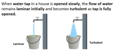
Reynolds Number: Reynolds Number is the ratio of Inertial forces to the Viscous forces. By knowing this number, one can describe the flow whether the flow is laminar, turbulent or transitional flow. There are three possibilities of the range of Reynolds Number: If Reynolds number < 2100 or 2300 ⟺ Laminar Flow If Reynolds number > 4000 ⟺ Turbulent Flow If 2300 < Reynolds number < 4000 ⟺ Transitional Flow In case of different shapes other than circle, the formula for Reynolds Number remain the same however diameter involves in the formula become Hydraulic Diameter which is given by: For pipe: Critical Reynolds Number ⟾ The Reynolds number at which the flow becomes turbulent Re cr For different shapes, the hydraulic diameters are given by: Completely Filled Flow In Closed Channel: If pipe is is considered to filled completely with closed channel, then following are the conditions which...
Intersection Of Solids: Solids are obtained by the combination of of two or more basic solids. When two or more solids combine, a definite curve/line is seen at their intersection. This curve/line is called curve/line of intersection (COI / LOI) and it is the result of inter-penetration of solids. Applications Of Intersection Of Solids: Designing a sheet metal objects. Automobile Parts. Moulding patterns. Forged end of connecting road. Intersection of two contacting surface, etc. Inter-Penetration Of Solids: When one solids penetrates another solids then their surfaces intersect and at the junction of intersection a typical curve is formed, which remains common to both solids. This curve is called Curve of Intersection and it is a result of inter-penetration of solids. Cases Of Intersection Of Solids: First we need to discuss the general solution steps of how we draw intersection of solids diagram. So know, we are going to discuss the basic steps:...
Types Of Lines And Its Uses: There are three types of types on the basis of thickness and they are: Visible Lines ↝ It represents features that can be seen in the current view. Hidden Lines ↝ It represents features that cannot be seen in the current view. Center Line ↝ It represents symmetry, path of motion, centers of circles,, axis of asymmetrical parts. Dimension and Extension Lines ↝ It indicates the sizes and location of features on a drawing. Placement Of Dimension Lines: Dimension should be outside the view. Dimension should be applied to one view. Dimension should be placed in a view that shows the distance in its true length. Dimension lines should be placed, in general 10 mm (1/2 in) away from the outlines from the view. Parallel lines should be placed uniformly. Values should be midway (auto centered) between the arrow heads, except when a center-line interferes. Dime...




Comments
Post a Comment
Questions or corrections are welcome. Please mention the relevant section and units. Do not post confidential project data or personal contact details. For project inquiries, use the Fluxiss contact page.