View Factor Orientation (or View factor or shape factor) plays an important role in radiation heat transfer. View factor is defined as, "fraction of radiation leaving surface 'i' and strike 'j' ". Summation Rule (View Factor) If there is are similar surfaces 'i' and 'j' , then: Blackbody Radiation Exchange Radiation Exchange between Opaque, Diffuse, Gray surfaces in an Enclosure 1. Opaque 2. Surfaces 3. Two surface enclosure Radiation Shield It is used to protect surfaces from radiation act like a reflective surface. References: Material from Class Lectures + Book named Fundamentals of Heat and Mass Transfer by Theodore L. Bergman + My knowledge. Photoshoped pics are developed. Some pics and GIF from Google. Videos from YouTube ( Engineering Sights ).
Get link
Facebook
X
Pinterest
Email
Other Apps
Kinetics Of A Particle: Force & Acceleration
Get link
Facebook
X
Pinterest
Email
Other Apps
-
Kinetics:
It is the branch of dynamics that deals with the relationship between the change in motion of a body the cause which changes it.
The base of kinetics is Newton's Second law of motion (F = ma).
Theory of Relativity → placed limitations on 2nd law of motion for describing particle motion.
Equations of motion fails to predict exact behavior of particle when it reaches speed of light 0.3 Gm/s.
There are two types of diagram which are described as follows:
Kinetic Diagram → shows inertial forces or net forces of body.
Free Body Diagram (FBD) → show all external forces on body.
If inertia force vector is treated in the same way as force vector → Equilibrium state is called Dynamic Equilibrium.
There are two types of frame of references but we are discussing only one which is:
Newtonian or Inertial Frame of Reference → state of rest or uniform velocity. Newton's laws only valid for non-rotating and non-accelerating reference system which is translating with constant velocity.
General Procedure For Problem Solving:
Select a convenient inertial coordinate system which can be rectangular, normal and tangential or cylindrical coordinates.
Draw FBD showing all external forces.
Draw the kinetic diagram showing inertia force, ma.
Apply equations of motion in scalar form.
Identify the unknowns and solve equation.
Kinematic relation may be applied
Equation Of Motion For a System Of Particles:
Equation of particle is valid for isolated system. Important points are:
Only for inertial frame of references.
Unbalanced force cause acceleration.
Inertial frame of reference does not rotate.
Applying equation of motion:
Mass → resistance to change in velocity (absolute quantity).
When all the forces acting on the particle can be resolved into cylindrical components easily.
Applying equation of motion, we get:
Frictional force always act along tangent in opposite direction.
The angle between tangent and radial line is given by:
Force on a system of particle is totally described as:
References:
Material from Class Lectures + Book named Engineering Mechanics Statics & Dynamics by R.C. Hibbeler (12th Edition) + from YouTube channel named Yiheng Wang for Engineering Dynamics Mechanics + my knowledge.
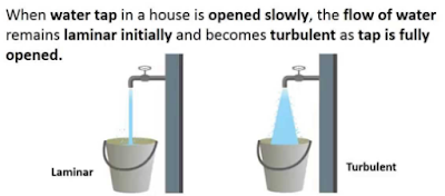
Reynolds Number: Reynolds Number is the ratio of Inertial forces to the Viscous forces. By knowing this number, one can describe the flow whether the flow is laminar, turbulent or transitional flow. There are three possibilities of the range of Reynolds Number: If Reynolds number < 2100 or 2300 ⟺ Laminar Flow If Reynolds number > 4000 ⟺ Turbulent Flow If 2300 < Reynolds number < 4000 ⟺ Transitional Flow In case of different shapes other than circle, the formula for Reynolds Number remain the same however diameter involves in the formula become Hydraulic Diameter which is given by: For pipe: Critical Reynolds Number ⟾ The Reynolds number at which the flow becomes turbulent Re cr For different shapes, the hydraulic diameters are given by: Completely Filled Flow In Closed Channel: If pipe is is considered to filled completely with closed channel, then following are the conditions which...
View Factor Orientation (or View factor or shape factor) plays an important role in radiation heat transfer. View factor is defined as, "fraction of radiation leaving surface 'i' and strike 'j' ". Summation Rule (View Factor) If there is are similar surfaces 'i' and 'j' , then: Blackbody Radiation Exchange Radiation Exchange between Opaque, Diffuse, Gray surfaces in an Enclosure 1. Opaque 2. Surfaces 3. Two surface enclosure Radiation Shield It is used to protect surfaces from radiation act like a reflective surface. References: Material from Class Lectures + Book named Fundamentals of Heat and Mass Transfer by Theodore L. Bergman + My knowledge. Photoshoped pics are developed. Some pics and GIF from Google. Videos from YouTube ( Engineering Sights ).
Mechanical Injection System: Used to inject fuel into the combustion chamber. Fuel speed > air speed at delivery point to atomize fuel. Amount of fuel delivered into the air stream going into the engine is controlled by pump which forces the fuel under pressure. A device used to initiate and control the combustion process is called Mechanical Injection System. Functional Requirements of Injection System: Metering of Fuel: Used to control fuel to meet speed and load requirements of the engine. Injection Timing: Have proper injection timing to obtain max. power, fuel economy and proper burning. It is done by Camshaft or Push rod (Rocker Arm) Mechanism . Proper Control of Injection Rate: To get desired heat release pattern during combustion. Proper Atomization of Fuel: Proper making of droplets to make best Air/Fuel mixture. Proper Spray Pattern: Distribution of droplets to ensure rapid mixing of fuel & air. Uniform Distribut...



Comments
Post a Comment
HI, we wI'll contact you later