Every loading condition on a ship or workboat starts with one question: is the vessel stable enough to sail? The fastest first answer is the transverse metacentric height, GM. This post sets out the hydrostatic fundamentals behind it, shows how free surface in slack tanks erodes it, explains how the inclining experiment fixes the lightship KG, and works through a loading condition for a small cargo vessel. It ends with the first checks against the IMO 2008 Intact Stability Code. It is a screening method, not a substitute for a full stability booklet. It also sits alongside our wider overview of marine engineering and naval architecture . Fundamentals: KB, BM, KM, KG and GM A floating vessel is in equilibrium when weight equals buoyancy and both act along the same vertical line. Buoyancy is the resultant of hydrostatic pressure on the hull, a topic we cover in pressure and fluid statics . When the vessel heels through a small angle, the underwater shape changes, and the centre of buo...
Get link
Facebook
X
Pinterest
Email
Other Apps
Fundamentals of Welding
Get link
Facebook
X
Pinterest
Email
Other Apps
-
Welding Process:
It is the permanent joining of two materials usually metals by coalescence which is induced by a combination of temperature, pressure and metallurgical conditions.
Types of Joints:
There are 5 types of joints which are described as follows:
1. Butt Joint:
The parts lie in the same plane and are joined to their edges.
2. Corner Joint:
Parts form a right angle and are joined at the corner of the angle.
3. Lap Joint:
It consist of two overlapping parts.
4. Tee Joint:
One part is perpendicular to the other in the shape of letter T.
5. Edge Joint:
Parts are parallel with atleast one of their edge is common and the joint is made at the common edges.
Types of Welds:
There are different types of welds which are described ahead:
1. Fillet Weld:
It is used to fill the edges of plates created by corner, lap and tee joints.
2. Groove Weld:
It usually require that the edges of the pats be shaped into a groove to facilitate weld penetration.
3. Spot Weld or Seam Weld:
Spot weld is a small fused section between the surfaces of two sheets or plates.
Seam weld consists of a more or less continuous fusion section between the two sheets and plates.
It is only for lap Joint.
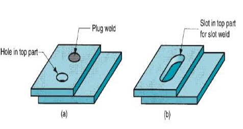
4. Plug Weld or Slot Weld:
They are used for attaching flat plates using one or more holes or slots in the top part and then filling with filler metal to fuse the two parts together.
5. Flange Weld:
It is made on the edges of two or more parts at least one of the parts being flanged.
Types of Welding:
There are two types of welding, namely:
Fusion Welding
Solid State Welding
1. Fusion Welding:
Welding process in which heat is used to melt the base metal.
A fusion welding operation in which no filler metal is added is referred as Autogeneous Weld.
Fusion Welding is further classified as:
A. Oxyfuel Gas Welding (OFW)
B. Arc Welding (AW)
C. Resistance Welding (RW)
A. Oxyfuel Gas Welding:
A welding process in which metal is melted by high temperature flame produced by combustion of a fuel gas and oxygen.
There are three types of flames which can be obtained by varying Oxygen-Acetylene ratio.
Neutral Flame ➤ Air and fuel ratio is 1:1 or 1.15:1 and temperature reaches to 3250℃.
Oxidising Flame ➤ Air and fuel ratio is 1.5:1 and temperature reaches to 3600℃.
Carbirizing Flame ➤ Air and fuel ratio is lesser than neutral flame ratio and temperature reaches to 3050℃.
B. Arc Welding:
A fusion welding process in which coalescence of metals is achieved by the heat from an electric arc between am electrode and the work.
If DC is used and electrode is made negative the condition is called Straight Polarity (SPDC) or Direct Current Electrode Negative (DCEN).
If DC is used and electrode is made positive the condition is called Reverse Polarity (RPDC) or Direct Current Electrode Positive (DCEP).
Types of Arc Welding:
There are two types of arc Welding:
1. Consumable Electrode Arc Welding:
There are four types of arc Welding which are described as follows:
I. Shielded Metal Arc Welding (SMAW):
It is a type of consumable arc Welding consisting of a filler metal rod coated with chemicals.
It is also called stick or covered Electrode.
Coated electrode vapourizes to provide a protective atmosphere.
Helps to stabilise arc, reduce weld metal spatter and increase efficiency of deposition.
And,
Now the final part looks like:
II. Flux Cored Arc Welding:
A type of arc Welding in which electrode is used in a tubular form and is filled with flux.
III. Gas Metal Arc Welding (GMAW):
A type of arc Welding in which consumable bare metal wire is used as electrode with shielding by flooding arc with a gas.
It is also called Metal Inert Gas Welding (MIG).
No need of volatilizing flux.
IV. Submerged Arc Welding:
It uses a continuous consumable bare wire electrode with arc shielding by a cover of granular flux consisting of silica, lime, manganese oxide, calcium fluoride and other compounds.
Electrode wire is fed automatically from coil.
Flux is introduced into joint just before arc from hopper.
It completely covers molten metal preventing sparks, spatter and radiation.
2. Non-Consumable Electrode Arc Welding:
There are different types of non-consumable electrode arc Welding but we discuss some of them:
I. Gas Tungsten Arc Welding (GTAW):
A type of arc Welding in which a non consumable tungsten electrode and inert gas for arc shielding is used.
It is also called Tungsten Inert Gas (TIG) or Wolfram Inert Gas (WIG) welding.
Used with or without filler metal.
Argon is use do produce stable arc.
II. Plasma Arc Welding (PAW):
It is a special form of Gas Tungsten Arc Welding in which Tungsten electrode is contained in a nozzle that focuses a high velocity stream of inert gas into arc region to form a high velocity intensely hot plasma Arc stream.
Temperature reaches to 16,500℃.
III. Stud Welding:
Welding process used for joining studs, screws, fasteners to the base metal.
The stud acts an electrode and it is chuked in a special weld gun that automatically controls the timing and power parameters.
C. Resistance Welding:
A group of fusion welding processes that uses a combination of heat and pressure to accomplish coalescence.
Heat is generated by passing current at the junction to be welded.
It is only for lap joints.
Types of Resistance Welding:
There are three types of Resistance Welding which we discussed ahead:
I. Resistance Spot Welding:
Resistance Welding process in which fusion of faying surfaces of a lap joint is achieved at one location by opposing electrodes.
The operation results in a fused zone between the two parts is called Weld Nugget.
Electrode shapes are hexagonal and square.
II. Resistance Seam Welding:
A type of resistance Welding in which electrode is used in the form of rotating wheel to produce a series of overlapping spots welds along lap joint.
Electrode shape is disk.
Use to produce air-tight joints.
III. Resistance Projection Welding:
A resistance Welding process in which coalescence occurs at one or more small contact points on the parts.
Contact points are determined by design of parts to be joined, projections, embossments or localized intersections of parts.
2. Solid State Welding (SSW):
A type of welding process in which coalescence is achieved by preassure alone or heat and pressure.
Factors for successful solid state weld are thaT the two faying surfaces should be very clean and in very close contact with each other to permit atomic bonding.
Types of Solid State Welding:
There are three types of Solid State Welding which we discussed ahead:
A. Diffusion Welding (DFW):
It uses heat and pressure with sufficient time for diffusion and coalescence to occur.
Temperature should be lesser than or equal to 0.5Tm.
B. Friction Welding (FRW):
A type of solid state welding in which coalescence is achieved by frictional heaT combined with pressure.
No filler metal, flux or shielding gas is required.
C. Ultrasonic Welding (USW):
A type of solid state welding in which two componets are held together by oscillairy shear stress to cause coalescence.
Temperature should be below melting point Tm.
Other Fusion Welding Processes:
We are discussing moat common used other fusion welding operations which are as follows:
I. Electron Beam Welding (EBW):
A fusion welding process in which heat for welding is provided by a highly focused and high intensity streams of electrons striking work surfaces.
II. Laser Beam Welding (LBW):
A fusion welding process in which coalescence is achieved by energy of a highly concentrated coherent light beam focused on joint.
Brazing & Soldering:
Brazing is the permanent joining of similar and dissimilar metals through the use of heat at temperature above 450℃ but below solidus temperature. Soldering is a type of brazing operation in which filler metal has a melting temperature below 450℃.
Reference:
University Notes
Book Fundamental of Modern Manufacturing 6th Edition by Mikell P. Groover
While welding a material its temperature increases which will result in increasing of reactivity with impurities around. To minimize the reaction between material and atmospheric impurities flux is used.
Due to flux a heated zone is created which increase the welding capabilities.
Questions or corrections are welcome. Please mention the relevant section and units. Do not post confidential project data or personal contact details. For project inquiries, use the Fluxiss contact page.
Reynolds Number: Reynolds Number is the ratio of Inertial forces to the Viscous forces. By knowing this number, one can describe the flow whether the flow is laminar, turbulent or transitional flow. There are three possibilities of the range of Reynolds Number: If Reynolds number < 2100 or 2300 ⟺ Laminar Flow If Reynolds number > 4000 ⟺ Turbulent Flow If 2300 < Reynolds number < 4000 ⟺ Transitional Flow In case of different shapes other than circle, the formula for Reynolds Number remain the same however diameter involves in the formula become Hydraulic Diameter which is given by: For pipe: Critical Reynolds Number ⟾ The Reynolds number at which the flow becomes turbulent Re cr For different shapes, the hydraulic diameters are given by: Completely Filled Flow In Closed Channel: If pipe is is considered to filled completely with closed channel, then following are the conditions which...
Intersection Of Solids: Solids are obtained by the combination of of two or more basic solids. When two or more solids combine, a definite curve/line is seen at their intersection. This curve/line is called curve/line of intersection (COI / LOI) and it is the result of inter-penetration of solids. Applications Of Intersection Of Solids: Designing a sheet metal objects. Automobile Parts. Moulding patterns. Forged end of connecting road. Intersection of two contacting surface, etc. Inter-Penetration Of Solids: When one solids penetrates another solids then their surfaces intersect and at the junction of intersection a typical curve is formed, which remains common to both solids. This curve is called Curve of Intersection and it is a result of inter-penetration of solids. Cases Of Intersection Of Solids: First we need to discuss the general solution steps of how we draw intersection of solids diagram. So know, we are going to discuss the basic steps:...
Types Of Lines And Its Uses: There are three types of types on the basis of thickness and they are: Visible Lines ↝ It represents features that can be seen in the current view. Hidden Lines ↝ It represents features that cannot be seen in the current view. Center Line ↝ It represents symmetry, path of motion, centers of circles,, axis of asymmetrical parts. Dimension and Extension Lines ↝ It indicates the sizes and location of features on a drawing. Placement Of Dimension Lines: Dimension should be outside the view. Dimension should be applied to one view. Dimension should be placed in a view that shows the distance in its true length. Dimension lines should be placed, in general 10 mm (1/2 in) away from the outlines from the view. Parallel lines should be placed uniformly. Values should be midway (auto centered) between the arrow heads, except when a center-line interferes. Dime...






Covering flux is used in Submerged arc welding why is that so?
ReplyDeleteWhile welding a material its temperature increases which will result in increasing of reactivity with impurities around. To minimize the reaction between material and atmospheric impurities flux is used.
DeleteDue to flux a heated zone is created which increase the welding capabilities.