View Factor Orientation (or View factor or shape factor) plays an important role in radiation heat transfer. View factor is defined as, "fraction of radiation leaving surface 'i' and strike 'j' ". Summation Rule (View Factor) If there is are similar surfaces 'i' and 'j' , then: Blackbody Radiation Exchange Radiation Exchange between Opaque, Diffuse, Gray surfaces in an Enclosure 1. Opaque 2. Surfaces 3. Two surface enclosure Radiation Shield It is used to protect surfaces from radiation act like a reflective surface. References: Material from Class Lectures + Book named Fundamentals of Heat and Mass Transfer by Theodore L. Bergman + My knowledge. Photoshoped pics are developed. Some pics and GIF from Google. Videos from YouTube ( Engineering Sights ).
It obtains its power by utilizing the energy of burnt gases and air which is at high temp and pressure by expanding through the several ring of fixed and moving blades.
It is similar to Steam Turbine but it uses Gas instead of Steam.
Turbine drives the compressor (as they are coupled to each other by a shaft).
Compressor absorbs power produced by turbine (lowers efficiency).
Compressor utilizes 40-45% of total power produced by Turbine.
A simple gas turbine cycle consists of:
Compressor
Combustion Chamber
Turbine
Steps:
Inlet (air comes in) → Compressed to a very high pressure (by compressor, Cpair) → which goes to combustion chamber where it burns (Cpgas) → produce combustion gases → hit turbine blades → it starts rotating → electricity produce → flue gases leaves the gas turbine.
Limitations:
When burning not started, compressor is run by an external source.
Small size, mass and initial cost per unit output.
Quick starting (as low as 10 Seconds) or Remote Control.
It uses variety of liquids/gases fuels including gasified coal, synthesis fuels.
Disadvantages:
Large compressor work input.
Brayton Cycle
It is the Ideal cycle for Gas Turbine Engines.
Notes:
Common design, pressure ratio of gas turbines (rp) ranges from 11 to 16.
In gas turbine powerplants, "Ratio of Compressor Work to Turbine Work is called Back Work Ratio" is very high.
Mostly,
Compressor Work Output = 0.5 x Turbine Work Output
Types of Gas Turbines
Open Cycle Gas Turbine → No Condenser (Cooler/Heat Exchanger), less efficient, greater emissions.
Closed Cycle Gas Turbine → Have Condenser.
Combined Cycle Power Plant
It couples two power cycles such that the energy discharged by heat transfer from one cycle is used partly as the input for the other cycle.
Temperature in a dry bottom cycle does not exceed 600℃ (Exit Boiler Temp).
High thermal irreversibility and a decrease in availability because of heat transfer from combustion gases to steam through such a large temp difference.
Types of Combined Cycle Power Plant
Gas Turbine-Steam Turbine Power Plant (GT-ST Power Plant)
Gas Turbine-Stirling Engine Power Plant
Diesel-Steam Turbine Power Plant (mostly in Textile Industry)
GT-ST Combined Cycle Power Plant With Supplementary Fuel Combustion
Major components used in GT-ST Power Plant:
Gas Turbine
Heat Recovery Steam Generator (HRSG)
Steam Turbine
Brayton Cycle is at the Top (High temp gas turbine power plant) while Rankine Cycle is at the bottom (Lower temp steam turbine power plant).
Steam Turbine utilizes the energy from the gas turbine exhaust as its input.
If temperature of the exhaust gas from GT is not up to mark (for desired power output), we use combustion chamber called Supplementary Combustion of Fuel.
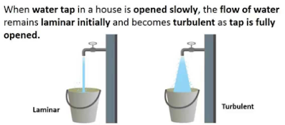
Reynolds Number: Reynolds Number is the ratio of Inertial forces to the Viscous forces. By knowing this number, one can describe the flow whether the flow is laminar, turbulent or transitional flow. There are three possibilities of the range of Reynolds Number: If Reynolds number < 2100 or 2300 ⟺ Laminar Flow If Reynolds number > 4000 ⟺ Turbulent Flow If 2300 < Reynolds number < 4000 ⟺ Transitional Flow In case of different shapes other than circle, the formula for Reynolds Number remain the same however diameter involves in the formula become Hydraulic Diameter which is given by: For pipe: Critical Reynolds Number ⟾ The Reynolds number at which the flow becomes turbulent Re cr For different shapes, the hydraulic diameters are given by: Completely Filled Flow In Closed Channel: If pipe is is considered to filled completely with closed channel, then following are the conditions which...
View Factor Orientation (or View factor or shape factor) plays an important role in radiation heat transfer. View factor is defined as, "fraction of radiation leaving surface 'i' and strike 'j' ". Summation Rule (View Factor) If there is are similar surfaces 'i' and 'j' , then: Blackbody Radiation Exchange Radiation Exchange between Opaque, Diffuse, Gray surfaces in an Enclosure 1. Opaque 2. Surfaces 3. Two surface enclosure Radiation Shield It is used to protect surfaces from radiation act like a reflective surface. References: Material from Class Lectures + Book named Fundamentals of Heat and Mass Transfer by Theodore L. Bergman + My knowledge. Photoshoped pics are developed. Some pics and GIF from Google. Videos from YouTube ( Engineering Sights ).
Mechanical Injection System: Used to inject fuel into the combustion chamber. Fuel speed > air speed at delivery point to atomize fuel. Amount of fuel delivered into the air stream going into the engine is controlled by pump which forces the fuel under pressure. A device used to initiate and control the combustion process is called Mechanical Injection System. Functional Requirements of Injection System: Metering of Fuel: Used to control fuel to meet speed and load requirements of the engine. Injection Timing: Have proper injection timing to obtain max. power, fuel economy and proper burning. It is done by Camshaft or Push rod (Rocker Arm) Mechanism . Proper Control of Injection Rate: To get desired heat release pattern during combustion. Proper Atomization of Fuel: Proper making of droplets to make best Air/Fuel mixture. Proper Spray Pattern: Distribution of droplets to ensure rapid mixing of fuel & air. Uniform Distribut...



Comments
Post a Comment
HI, we wI'll contact you later