View Factor Orientation (or View factor or shape factor) plays an important role in radiation heat transfer. View factor is defined as, "fraction of radiation leaving surface 'i' and strike 'j' ". Summation Rule (View Factor) If there is are similar surfaces 'i' and 'j' , then: Blackbody Radiation Exchange Radiation Exchange between Opaque, Diffuse, Gray surfaces in an Enclosure 1. Opaque 2. Surfaces 3. Two surface enclosure Radiation Shield It is used to protect surfaces from radiation act like a reflective surface. References: Material from Class Lectures + Book named Fundamentals of Heat and Mass Transfer by Theodore L. Bergman + My knowledge. Photoshoped pics are developed. Some pics and GIF from Google. Videos from YouTube ( Engineering Sights ).
Failure is further divided into following types depending on percentage elongation (%EL).
Very Ductile ⇔ if %EL > 20%, which can be converted into wires (like gold, etc.)
Moderately Ductile ⇔ if 20% < %EL < 5%, almost all metals.
Brittle ⇔ if %EL < 5%, flat deformation.
Failure is further divided into following depending on crack propagation.
Trans-Granular Fracture ⇔ If crack propagates within the grains. If plane is weak, crack propagates through grains.
Intra-Granular Fracture ⇔ If crack propagates through the boundary of grains, since boundary is amorphous (weak).
Engineering Fracture Design
Stress concentration increases with the increase in sharpness of edges (so avoid cornering in design), means your corner should have larger fillet radius.
If difference between width 'W' and height 'h' is higher ↠ convergence of stress line is greater, so higher stress concentration.
Cracks having sharp tips propagate easier than cracks having blunt tips.
If you see crack ↠ stop it by punching it to decrease convergence, stress concentration decreases.
Elastic Strain Energy ↠ energy stored in material as it is elastically deformed.
Critical Energy
Crack propagates if crack tip stresses(σm) exceeds a critical stress(σc).
For ductile material ↠ replace (γS) with (γs + γp), where γp = plastic deformation energy.
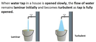
Reynolds Number: Reynolds Number is the ratio of Inertial forces to the Viscous forces. By knowing this number, one can describe the flow whether the flow is laminar, turbulent or transitional flow. There are three possibilities of the range of Reynolds Number: If Reynolds number < 2100 or 2300 ⟺ Laminar Flow If Reynolds number > 4000 ⟺ Turbulent Flow If 2300 < Reynolds number < 4000 ⟺ Transitional Flow In case of different shapes other than circle, the formula for Reynolds Number remain the same however diameter involves in the formula become Hydraulic Diameter which is given by: For pipe: Critical Reynolds Number ⟾ The Reynolds number at which the flow becomes turbulent Re cr For different shapes, the hydraulic diameters are given by: Completely Filled Flow In Closed Channel: If pipe is is considered to filled completely with closed channel, then following are the conditions which...
View Factor Orientation (or View factor or shape factor) plays an important role in radiation heat transfer. View factor is defined as, "fraction of radiation leaving surface 'i' and strike 'j' ". Summation Rule (View Factor) If there is are similar surfaces 'i' and 'j' , then: Blackbody Radiation Exchange Radiation Exchange between Opaque, Diffuse, Gray surfaces in an Enclosure 1. Opaque 2. Surfaces 3. Two surface enclosure Radiation Shield It is used to protect surfaces from radiation act like a reflective surface. References: Material from Class Lectures + Book named Fundamentals of Heat and Mass Transfer by Theodore L. Bergman + My knowledge. Photoshoped pics are developed. Some pics and GIF from Google. Videos from YouTube ( Engineering Sights ).
Mechanical Injection System: Used to inject fuel into the combustion chamber. Fuel speed > air speed at delivery point to atomize fuel. Amount of fuel delivered into the air stream going into the engine is controlled by pump which forces the fuel under pressure. A device used to initiate and control the combustion process is called Mechanical Injection System. Functional Requirements of Injection System: Metering of Fuel: Used to control fuel to meet speed and load requirements of the engine. Injection Timing: Have proper injection timing to obtain max. power, fuel economy and proper burning. It is done by Camshaft or Push rod (Rocker Arm) Mechanism . Proper Control of Injection Rate: To get desired heat release pattern during combustion. Proper Atomization of Fuel: Proper making of droplets to make best Air/Fuel mixture. Proper Spray Pattern: Distribution of droplets to ensure rapid mixing of fuel & air. Uniform Distribut...



Comments
Post a Comment
HI, we wI'll contact you later