View Factor Orientation (or View factor or shape factor) plays an important role in radiation heat transfer. View factor is defined as, "fraction of radiation leaving surface 'i' and strike 'j' ". Summation Rule (View Factor) If there is are similar surfaces 'i' and 'j' , then: Blackbody Radiation Exchange Radiation Exchange between Opaque, Diffuse, Gray surfaces in an Enclosure 1. Opaque 2. Surfaces 3. Two surface enclosure Radiation Shield It is used to protect surfaces from radiation act like a reflective surface. References: Material from Class Lectures + Book named Fundamentals of Heat and Mass Transfer by Theodore L. Bergman + My knowledge. Photoshoped pics are developed. Some pics and GIF from Google. Videos from YouTube ( Engineering Sights ).
Get link
Facebook
X
Pinterest
Email
Other Apps
Crystal Structures
Get link
Facebook
X
Pinterest
Email
Other Apps
-
Crystalline Solids and it's Structures
Crystalline Solids are defined as, "atoms arranged in periodic manner over long atomic distances in 3D patterns".
It deals with the unit cell (smallest part of structure).
If no 3D pattern ⇔ non-crystalline or amorphous solids.
Single Crystal ⇔ all unit cells interlock in the same way in the same orientation.
Polycrystalline Material ⇔ collection of small crystals (or grains) having random crystallographic orientation.
There are two types of unit cells, namely
Hard-Sphere unit cell
Reduced-Sphere unit cell
Types of Crystal Structures
Following are the types of crystal structures:
1. Face-Centered Cubic (FCC) Crystal Structure
It is defined as, "Unit cell of cubic geometry in which atoms are located at each of corners and centers of all cubic faces".
Each corner atom is shared among 8 unit cells.
Face-centered atom shared with 2 unit cells.
2. Body-Centered Cubic (BCC) Crystal Structure
It is defined as, "Cubic unit cell with atoms located at all eight corners and single atom at cubic center".
Center and corner atoms touch one another along cube diagonals.
Coordination number of BCC is 8.
3. Hexagonal Close-Packed (HCP) Crystal Structure
It is defined as, "Unit cell having cubic structure and have top and bottom faces consist of 6 atoms that forms regular hexagon and surround a single atom in the center".
Three additional atoms ⇔ provided to a plane between top and bottom face.
Coordination number is 12.
Atomic Packing factor is 0.74.
Stacking Sequence
It is defined as, "conversion of 2D layers to 3D structures to minimize empty spaces".
Important Terms
Point Coordinates ↔ are lattice parameters. It can be used to define which plane is more denser.
Crystallographic Directions ↔ Line between two points.
Crystallographic Planes ↔ Set of equally spaced planes that may be supposed to pass through the center of atoms in a crystal.
Linear Atomic Density ↔ It is the ratio between number of atoms and unit length of direction vector.
Theoretical Density ↔ Crystal structure of metallic solid permits computation of its theoretical density through the relationship.
References:
Material from Class Lectures + Book named Materials Science and Engineering: An Introduction by Callister and Rethwick + my knowledge.
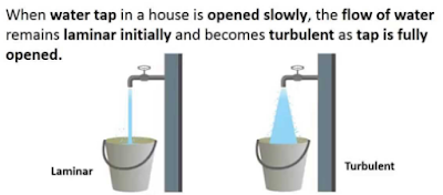
Reynolds Number: Reynolds Number is the ratio of Inertial forces to the Viscous forces. By knowing this number, one can describe the flow whether the flow is laminar, turbulent or transitional flow. There are three possibilities of the range of Reynolds Number: If Reynolds number < 2100 or 2300 ⟺ Laminar Flow If Reynolds number > 4000 ⟺ Turbulent Flow If 2300 < Reynolds number < 4000 ⟺ Transitional Flow In case of different shapes other than circle, the formula for Reynolds Number remain the same however diameter involves in the formula become Hydraulic Diameter which is given by: For pipe: Critical Reynolds Number ⟾ The Reynolds number at which the flow becomes turbulent Re cr For different shapes, the hydraulic diameters are given by: Completely Filled Flow In Closed Channel: If pipe is is considered to filled completely with closed channel, then following are the conditions which...
Gear Forming by Machining Formation of gear through machining consists of following methods: Form Milling by Disc Cutter Form Milling by End Mill Cutter Shaper, Planner and Slotter Broaching 1. Form Milling by Disc Cutter It is defined as, " Tooth is cut one by one by plunging the rotating cutter into the blank " . Each gear needs a separate cutter. 8 - 10 standard cutters are available for producing 12 - 120 teeth gears. Used for big spur gears of large pitch. 2. Form Milling by End Mill Cutter It includes the cutting of tooth at a time and then indexed for the next tooth space for cutting. For a small volume production of low precision gears. Set of 10 cutters ↠ 12 - 120 teeth gears . Used for teeth of large gears/module. To reduce cost, same cutter is often used for multiple sized gears resulting in profile errors . Characteristics: Use of Hardened stainless steels (HSS) form milling cutters. Use of Ordinary milling machines. Low production rate (need of indexing...
Mechanical Injection System: Used to inject fuel into the combustion chamber. Fuel speed > air speed at delivery point to atomize fuel. Amount of fuel delivered into the air stream going into the engine is controlled by pump which forces the fuel under pressure. A device used to initiate and control the combustion process is called Mechanical Injection System. Functional Requirements of Injection System: Metering of Fuel: Used to control fuel to meet speed and load requirements of the engine. Injection Timing: Have proper injection timing to obtain max. power, fuel economy and proper burning. It is done by Camshaft or Push rod (Rocker Arm) Mechanism . Proper Control of Injection Rate: To get desired heat release pattern during combustion. Proper Atomization of Fuel: Proper making of droplets to make best Air/Fuel mixture. Proper Spray Pattern: Distribution of droplets to ensure rapid mixing of fuel & air. Uniform Distribut...




Comments
Post a Comment
HI, we wI'll contact you later