View Factor Orientation (or View factor or shape factor) plays an important role in radiation heat transfer. View factor is defined as, "fraction of radiation leaving surface 'i' and strike 'j' ". Summation Rule (View Factor) If there is are similar surfaces 'i' and 'j' , then: Blackbody Radiation Exchange Radiation Exchange between Opaque, Diffuse, Gray surfaces in an Enclosure 1. Opaque 2. Surfaces 3. Two surface enclosure Radiation Shield It is used to protect surfaces from radiation act like a reflective surface. References: Material from Class Lectures + Book named Fundamentals of Heat and Mass Transfer by Theodore L. Bergman + My knowledge. Photoshoped pics are developed. Some pics and GIF from Google. Videos from YouTube ( Engineering Sights ).
Get link
Facebook
X
Pinterest
Email
Other Apps
Stress and Strains
Get link
Facebook
X
Pinterest
Email
Other Apps
-
Stress:
It is defined as force per unit area.
Stress is in direction of force because it is directly proportional to the strain produce which have same direction as that of applied force.
It is a resistance (not a reaction) of material having same direction as that of force.
Stress in Steel Bar > Stress in Rubber Bar ⇔ Because steel have more resistance than rubber.
Ques: Does a rigid body produce stress under the action of load?
No, since there is no relative displacements in rigid body (no change in shape or size). So strain is equal to zero. Since, stress ∝ strain, so stress is equal to zero.
Ques: Is it good to have larger amount of stress produced in material?
No, higher stresses means more chances of failure (fracture). In order to make parts stronger, you need to reduce stress amount produced. For this use stronger material and thicker cross-section.
Types of Stresses:
Normal Stress ⇔ Stress applied perpendicular to cross-section which results in increase or decrease of length.
Shear Stress ⇔ Stress applied parallel to the surface results in angular deformation. It is in opposite direction as that of applied force.
Tensile Stress (+σ) ⇔ Normal Stress applied to elongates a surface.
Compressive Stress (-σ) ⇔Normal Stress applied to compress a surface.
Important Terms:
Prismatic Bar ⇔ Bar having constant cross-section.
Homogenous Bar ⇔ Bar having same composition.
Isotropic Bar ⇔ Bar having same properties in x, y, z directions.
Max. Average Normal Stress ⇔ If bar is subjected to external loads (no constant stress). Hence, stress is present at location where ratio P/A is maximum.
Complementary Property of (Pure) Shear:
Shear stresses having same magnitude but opposite directions are referred to as Complementary Property of Pure Shear.
Single Shear (τ = V/A) ⇔ If load is applied on one plane result in division of 2 parts.
Double Shear (τ = V/2A) ⇔ If load is applied on two plane result in division of 3 parts.
Due to normal or shear stress applied on a structural member, stresses or strains are induced which cause failure. To do the analysis, we divide components into small units showing state of stress.
Each force of cube have one normal and two shear stress.
Ques: Why cube showing state of stress have 1 normal and 2 shear stress on one plane?
If cube is placed on a surface there is only one perpendicular plane, so only one Normal Stress.
If cube is lying on a surface there is only one plane having 2 dimensions parallel to the surface, so two Shear Stresses.
Allowable or Normal Stress:
It is the amount of stress that we permit in material to avoid fracture.
We limit stress to make structural member of mechanical element safe.
To ensure safety, let load be lower than allowable stress and use thicker cross-section.
Ques: What is the value of allowable stress, is it constant?
It cannot be a constant. It depends on load, geometry, supports, orientation and material.
It is defined as, Amount of stress at which material fails (i.e. material before becoming non-functional).
It is a material property.
It describe the strength of material.
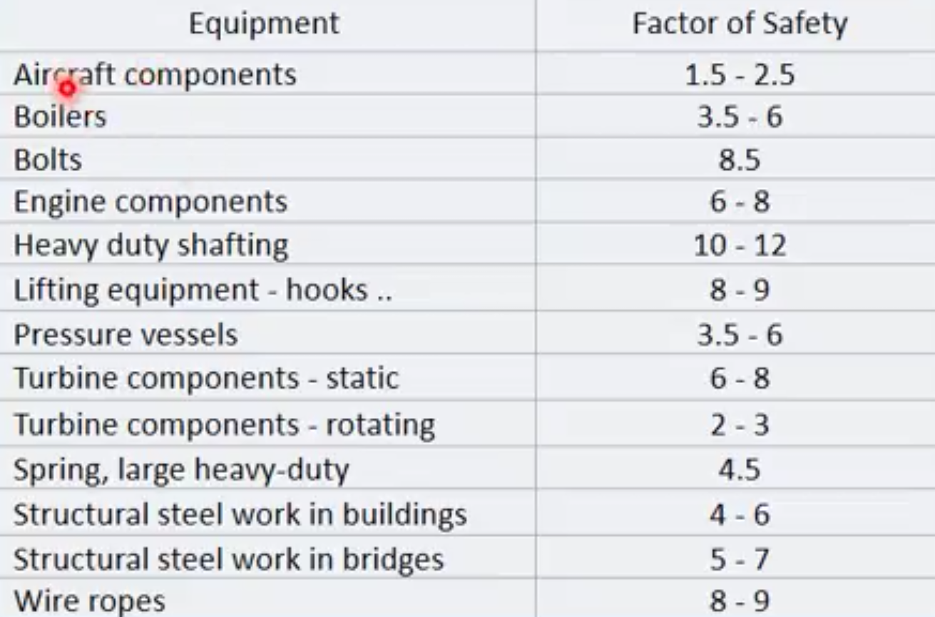
Factor of Safety:
It is the ratio of Failure load to the allowable load.
Actual loads is not equal to load we calculate, there are some uncertainties (due to this, stress increase and material fails):
Measurement errors due to the error in fabrication and assembly of components.
No consideration of vibrations, impact and accidental loadings in design.
Strength decreases due to atmospheric corrosion, decay, weather deteriorate occurs.
Wood, concrete, fiber-reinforced composites show variability in mechanical properties.
F.S. in design of aircraft or space vehicle components should be close to 1 to reduce weight.
Larger F.S. means have less chances of failure, thicker, heavier, expensive.
Lesser F.S. means have more chances of failure, thinner, lighter.
Determinacy of System ↣ If number of equations = number of unknowns.
Indeterminacy of System ↣ If number of equations < number of unknowns.
Neutral System ↣ If number of equations > number of unknowns.
Stress Induced in Pressure Vessel:
When pressure is applied, pressure loading comes into play which results in stresses.
Pressure stresses depends on radius of pipe, shape of vessel and pressure applied.
Types of Pressure Vessel:
There are two types of pressure vessel which are discussed ahead:
Thin Wall Pressure Vessel↣ If ratio of inner radius to wall thickness is greater than and equals to 10 (inner radius/wall thickness >= 10)
Thick Wall Pressure Vessel ↣ It does not depend on r/t ratio rather it depends on Elasticity Solution.
1. Thin Wall Pressure Vessel:
There are two types of Thin Wall Pressure Vessel which are discussed ahead:
a. Cylindrical Pressure Vessel:
There are are two types of stresses applied Longitudinal (or Axial) Stresses and Circumferential (or Hoop) Stresses.
a. Spherical Pressure Vessel:
There are are two types of stresses applied Longitudinal (or Axial) Stresses and Circumferential (or Hoop) Stresses and they are equal to each other in case of Spherical Pressure Vessel.
Strain:
It is defined as the Deformation of body under applied stress.
Types of Strains:
Normal Strain ↣ change in length along one specific directions.
Shear Strain↣ change in angle with respect to two specific directions (or deformation perpendicular to original length).
References:
Material from Class Lectures + Book named Engineering Mechanics of Materials by R.C. Hibbeler (10th Edition) + my knowledge.
Projection: The term Projection is defined as: Presentation of an image or an object on a surface. The principles used to graphically represent 3-D objects and structures on 2-D media and it based on two variables: Line of Sight. Plane of Projection. Line of Sight & Plane of Projection: Line of sight is divided into 2 types: Parallel Projection Converging Projection & A plane of projection is an imaginary flat plane upon which the image created by the lines of sight is projected. Orthographic Projection: When the projectors are parallel to each other and perpendicular to the plane of projection. The lines pf sight of the observer create a view on the screen. The screen is referred to as the Plane of Projection (POP). The lines of sight are called Projection lines or projectors. Rules of Orthographic Projection: Edges that are parallel to a plane of projection appear as lines. Edges that are incl...
Advance High Strength Steel Conventional low carbon mild steel has simpler ferritic structure (α-iron) and good ductility. Common type of HSS is High Strength Low Alloy (HSLA) ⇥ has yield strength 550 - 690 N/sq.mm . Manganese ⇥ supporter (stabilizer) of ferrite. Conventional HSS : Is single-phase ferritic steel with a potential for some pearlite in C-Mn steel. Lower strain hardening capacity. Advance HSS : primarily steel with a microstructure containing a phase other than ferrite, pearlite, cementite. Higher strain hardening capacity. Case Study of Automobile There are three different zones in a car: Crumple Zone (Front & Back) Middle Compartment Safety Cage Some important points about these zones are: Crumple Zone ⇥ Made with those materials which absorb maximum amount of energy. Safety Cage ⇥ Multiple areas (like cabins, structural elements). Areas of Safety cage are described ahead: Cabins (Blue Areas) ⇥ Should have high streng...
ADVANTAGES OF HYDROGRAPHIC SURVEY Accurate hydrographic survey and nautical charts yields many social benefits and contribute alot in making our life even more luxurious. 1.Safety of navigation is the single most important result of hydrography. This allows ships to safely travel in and out of ports, saving lives and property and protecting the environment. 2. National Security requires that navies successfully navigate coastal waterways. 3. Maritime commerce drives the global economy and depends on safety of navigation. 4. Humanitarian relief in the aftermath of a natural disaster frequently arrives on a ship. Until a clear and safe route to shore is established by hydrographers, supplies cannot reach those in need. 5. Environmental management in coastal areas depends on knowledge of changes in the marine environment. Hydrographic surveys determine changes to bathymetry and seafloor characteristics. 6. Commercial fishing uses nautical charts...


Comments
Post a Comment
HI, we wI'll contact you later