View Factor Orientation (or View factor or shape factor) plays an important role in radiation heat transfer. View factor is defined as, "fraction of radiation leaving surface 'i' and strike 'j' ". Summation Rule (View Factor) If there is are similar surfaces 'i' and 'j' , then: Blackbody Radiation Exchange Radiation Exchange between Opaque, Diffuse, Gray surfaces in an Enclosure 1. Opaque 2. Surfaces 3. Two surface enclosure Radiation Shield It is used to protect surfaces from radiation act like a reflective surface. References: Material from Class Lectures + Book named Fundamentals of Heat and Mass Transfer by Theodore L. Bergman + My knowledge. Photoshoped pics are developed. Some pics and GIF from Google. Videos from YouTube ( Engineering Sights ).
Get link
Facebook
X
Pinterest
Email
Other Apps
Keys and Coupling
Get link
Facebook
X
Pinterest
Email
Other Apps
-
Keys
It is defined as, "a machine element used to transmit motion or torque to other components".
It is usually made up of mild steel, carbon steel.
Mount on shaft and placed parallel to shaft axis.
Act as temporary fastener.
Subjected to crushing (compression) and shearing stresses.
Hub (Coupling of shaft) ↠ Internal diameter of pulley that connects with shaft.
Keyway ↠ Space in which key is inserted.
Broaching ↠ Removal of keyway from hub.
Milling ↠ Addition of key with shaft.
Types of Keys
Key selection depends on torque magnitude transmitted, type of loading, cost. Types of keys are discussed ahead:
1. Sunk Keys
Most commonly used key.
Power is transmitted due to shear resistance of key.
For heavy duty applications (positive drive due to no slip).
Types of Sunk Keys
a. Rectangular Sunk Key
Flat key, more stable than square key and have taper.
b. Square Sunk Key
Key is in square shape and have taper.
Use for mounting pulleys, gears on shafts.
If diameter of shaft > 17 mm ↠ use square sunk key.
c. Parallel Sunk Key
It can be rectangular or square but having no taper (taperless key).
Used for mating piece (pulley, gear, etc).
d. Gib-head Taper Sunk Key
Rectangular key with a head at one end.
Head is provided to facilitate removal of key.
Taper surface increases frictional force and tighten joint.
e. Feather Sunk Key
Parallel key (fixed on shaft with screw or hub) which permits rotation as well as relative axial movement between them as well.
Used in clutches, gear shifting devices.
f. Woodruff Sunk Key
Semi circular key.
Extra depth in shaft and hub ↠ increase stress concentration which reduces strength.
2. Tangent or Kennedy Keys
Rectangular or parallel keys in pairs placed at angles and diagonally.
Each key withstand torsion in one direction.
Used in large, heavy duty shafts.
Due to diagonally added keys ↠ area decreases shear forces increases.
3. Round Keys
Circular section key which fit into holes drilled partly in shaft and partly in hub.
For low power drives.
4. Splines
Keys are made integral with shaft and keyway with hub so called Splined Shafts.
Used when there is relative axial motion between shaft and hub like gear shifting mechanisms.
For heavy duty shaft (no slip), 100% power transfer.
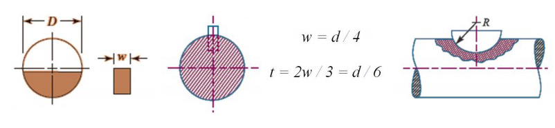
Force Acting on a Sunk Key
Shaft Coupling or Coupling
It is defined as, "an element used to connect two shafts so that power from driving shaft is transmitted to driven shaft without any change of speed".
Used in connecting motor and generator.
Hold shaft in perfect alignment.
Reduce the transmission of shock loads.
There are misalignment's between driving and driven shafts which are discussed ahead
Offset ↠ used when shafts axes are parallel.
Angular ↠ used when shafts axes are intersecting at their center.
Offset and Angular ↠ used when shafts are intersecting other than their center.
Types of Couplings
There are two types of coupling which are described below:
1. Rigid Coupling
It is used to connect perfectly aligned shafts.
No lubrication required so no movable parts.
Can absorb shocks and vibrations.
Types of Rigid Couplings
Following are the types of rigid couplings.
a. Sleeve or Muff Coupling
Consist of hollow cylinder (made of cast iron) which is fitted over the ends of two shafts by means of gib-head key.
Used up to 70 mm diameter shafts.
If using 2 keys (general case) ↠ Length of Hub/Sleeve = 0.5 x Length of Key.
If using 1 key ↠ Length of Hub/Sleeve = Length of Key.
b. Clamp or Split Muff or Compression Coupling
A type of muff and rigid coupling in which muff is divided into 2 halves and are bolted together.
Stud Bolts ↠ placed in radial direction for the alignment of upper and lower surface.
Single key is fitted in keyways of both shafts.
Used for low and moderate speeds and not for shock loads.
c. Flange Coupling
It have two separate flanges of cast iron mounted on shaft and keyed to it.
One flange ↠ projected portion (spigot) maintain alignment with another flange called Socket.
Bolts and nuts are used to join flanges in axial direction.
Most commonly used coupling, for high speed and large diameter shafts.
Types of Flange Coupling
Unprotected Type Flange Coupling ↠ Nuts and bolts are placed on the outside of coupling.
Protected Type Flange Coupling ↠ Increase the thickness of coupling provided nuts and bolts within the coupling.
Marine Type Flange Coupling ↠ Shaft and coupling are integral part and pinned to assemble.
Design of Flange Coupling
2. Flexible Coupling
This coupling is used to join ends of shafts having lateral and angular misalignment.
Chances of power loss due to misalignment of shafts.
It has flexible elements which can absorbs shocks and vibrations.
Misalignment causes temperature change, bearing wear, vibrations.
Types of Flexible Coupling
a. Bushed-Pin Flexible Coupling
Modification of flange coupling in which we use bush and pin to join flanges rather than nuts and bolts.
Pin is fixed on output flange bu nuts.
Rubber bush is provided to input flange to absorb shocks and vibrations. To avoid wear, it is Brass lined at the inner.
Clearance should be placed between two halves (5 mm) to accommodate misalignment.
Require more axial space because Outer diameter of flange = 4 x Diameter of Shaft.
b. Oldham Coupling
It is used to join 2 shafts having lateral misalignment or connect two parallel shafts which are at a small distance apart.
It has 2 flanges: Hub and Central floating part (mostly black) with 2 keyway.
Central floating part is held together by pin and passed through flanges and floating part.
It can allow maximum lateral misalignment of 5% of the diameter of shaft and allow 1-degree of angular misalignment.
Shaft diameter should be slightly greater whole number.
c. Universal or Hooke's Coupling
It is used to connect two shafts whose axes intersects at small angles.
It can allow maximum misalignment of 30-degrees (safe ↠ 5-15 degrees).
References:
Material from Class Lectures + Book named Mechanical Engineering Design by Shigley (8th Edition) + my knowledge.
Projection: The term Projection is defined as: Presentation of an image or an object on a surface. The principles used to graphically represent 3-D objects and structures on 2-D media and it based on two variables: Line of Sight. Plane of Projection. Line of Sight & Plane of Projection: Line of sight is divided into 2 types: Parallel Projection Converging Projection & A plane of projection is an imaginary flat plane upon which the image created by the lines of sight is projected. Orthographic Projection: When the projectors are parallel to each other and perpendicular to the plane of projection. The lines pf sight of the observer create a view on the screen. The screen is referred to as the Plane of Projection (POP). The lines of sight are called Projection lines or projectors. Rules of Orthographic Projection: Edges that are parallel to a plane of projection appear as lines. Edges that are incl...
Flywheel It is defined as, " a machine element which serves as reservoir which stores energy during the period when energy supply is more than the requirement and releases it when energy is less than requirement " . Used in IC, reciprocating (compressors or pumps) engines, presses, etc. Excess energy is stored in flywheel and release to crankshaft during other strokes in which no energy is developed. If space is small ↠ use small diameter and solid flywheel . If space is not limited (like for presses, crushing machine, hammering machine) ↠ use large diameter and hollow flywheel . Purpose of flywheel is to: reduce amplitude of speed fluctuation (sinusoidal) for constant power output. reduce maximum torque required. energy stored and release when needed during cycle. Parts of flywheel are Rim ↠ outer portion of flywheel (which is like a wheel). Hub ↠ center part which is installed on shaft. Arms or Needle ↠ rods joining rim to ...
Angles & Directions Angles are also called bearings. Bearings are the acute angles between lines and meridians. They are divided into following types. Related Terms : Meridian : Imaginary line joining North and South poles. Declination : Difference between magnetic and true meridians. Azimuth : Clockwise angle taken from Geodatic North. * If area is greater ➤ use Geodatic North * If area is smaller ➤ use Magnetic North Magnetic Declination maybe towards East or West. For east ➤ Magnetic bearing=true bearing - Declination For west ➤ Magnetic bearing=true bearing + Declination Forward Bearing : Bearing taken in the direction of traverse. Backward Bearing : Bearing taken in opposite direction of traverse. Forward bearing - Backward bearing=180 For anti-clockwise : FB of line = BB of previous line + angle Example: In an anti-clockwise traverse <A=102'30',...


Comments
Post a Comment
HI, we wI'll contact you later