View Factor Orientation (or View factor or shape factor) plays an important role in radiation heat transfer. View factor is defined as, "fraction of radiation leaving surface 'i' and strike 'j' ". Summation Rule (View Factor) If there is are similar surfaces 'i' and 'j' , then: Blackbody Radiation Exchange Radiation Exchange between Opaque, Diffuse, Gray surfaces in an Enclosure 1. Opaque 2. Surfaces 3. Two surface enclosure Radiation Shield It is used to protect surfaces from radiation act like a reflective surface. References: Material from Class Lectures + Book named Fundamentals of Heat and Mass Transfer by Theodore L. Bergman + My knowledge. Photoshoped pics are developed. Some pics and GIF from Google. Videos from YouTube ( Engineering Sights ).
Get link
Facebook
X
Pinterest
Email
Other Apps
Introduction To Engineering Drawing
Get link
Facebook
X
Pinterest
Email
Other Apps
-
Engineering Drawing:
Engineering drawing is a technical drawing used to define the requirements for engineering products or products.
Tools Used for Manual Drawing:
Tools used for drawing are listed below:
Technical Drawing Board
T-Squares
Triangles
Adhesive Tape
Pencils ( HB, 2HB for thick line and 4HB for thin line )
Sandpaper
Compass
Pencil Eraser
Erasing Shield
Circle Template
Tissue Paper
Sharpener
Clean Paper
Types of Lines Used in Engineering Drawing:
Types of line and their usage are given below:
Drawing Scales:
Scale is the ratio of the linear dimension (length, size) of an element of an object in the drawing to the real linear dimension of the same element of the object.
Geometric Construction
1. Drawing Bisectors:
A geometric line which divide a line into two equal parts by drawing arc are called Bisectors.
a. Method of Bisecting A Line:
First draw the line AB.
At point A with radius more than half of distance of length AB, draw arc above and below the line AB.
Repeat the procedure at point B.
Draw line XY which is a perpendicular bisector.
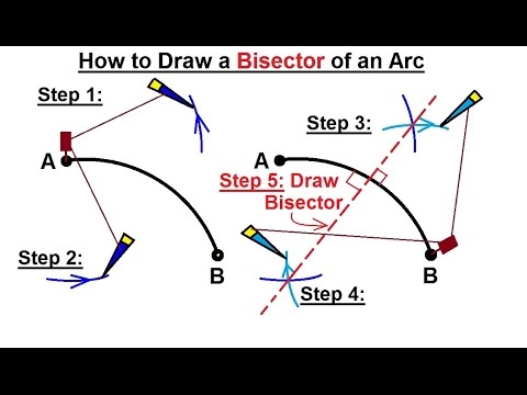
b. Method of Bisecting An Arc:
First draw an arc AB.
At point A with definite radius, draw arc above and below the arc AB.
Repeat the procedure at point B.
Draw line passing through the intersected points which is a perpendicular bisector.
b. Method of Bisecting An Angle:
First draw angle <AOB.
At point O with definite radius, draw arc intersecting line OA, then at intersecting point with the same radius, draw an arc.
At point O with definite radius, draw arc intersecting line OB, then at intersecting point with the same radius, draw an arc, intersecting the previous arc.
Draw line passing through the intersected point and point O.
2. Drawing Perpendiculars:
a. Perpendicular To A Given Line With Point P:
Draw a line AB with point P.
Consider a point O in space and draw circle intersecting at point P and C.
Join C and O with a line and extends it to point Q.
Draw a line from point Q to point P which is a perpendicular.
b. Perpendicular To A Given Line From Outside Point P:
Draw a line AB with outside to that line.
Draw an arc intersecting line AB at any two points.
Without changing the radius, draw arcs with both intersected point .
Draw a line from outside point to the arc intersected point which is a perpendicular.
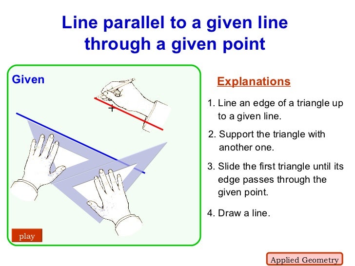
3. Drawing Parallel Lines:
a. Parallel Line Passing Through A Point:
Draw a line to which parallel line is to be drawn.
Set your Triangles as shown in the figure.
Slide upper triangle and by reaching that point, draw a line.
b. Parallel Line Passing Through Two Points At A Particular Distance"
Draw a line to which parallel line is to be drawn.
Select two points on the line.
With radius equal to the required distance, draw arcs with those points.
Draw a tangent line touching both small circle which is a parallel line.
4. Dividing:
a. A Line Into Required Equal Parts:
Draw s straight line AB.
From A draw AD of any length making any acute angle with AB.
With the compass mark off AD into required number of divisions lets say 7.
Join 7 to point B and then draw parallel line from points 6,5,4,3,2,1 which has to be parallel with line 7B.
b. Dividing A Circle Into 12 Equal Parts:
Draw the circle of radius R and draw diagonals AB and CD.
With point A and radius R, draw small arc at 2 and 10.
Similarly, repeat same process at points B,C,D.
Then draw lines.
5. Drawing Arcs:
a. Arc Touching Two Rectangular Lines:
Let r be the radius of required arc.
Draw rectangular lines.
Draw parallel lines to both rectangular lines at the distance of r.
Draw an arc at that intersected point O which touches both lines.
b. Arc Touching Two Straight Lines At Any Angle:
Let r be the radius of required arc.
Draw two lines at any angle.
Draw parallel lines to both lines at the distance of r.
Draw an arc at that intersected point O which touches both lines.
c. Arc Touching Tangentially A Straight Line and A Circle:
Let R be the radius of required arc.
Draw a straight line.
Draw parallel line to line at the distance of R.
Draw an arc with circle (having radius r) center at a distance R-r intersecting the line.
Draw an arc from point O.
d. Arc Touching Tangentially To Two Excluding Circles:
Let x be the radius of required arc.
Draw two circles having radii r and R.
With center O, draw an arc of radius (x+r).
With center P, draw an arc of radius (x+R) intersecting the previous arc.
With Point C, draw an arc of radius x which touches tangentially to both excluding circles.
e. Arc Touching Tangentially To One Excluding and One Including Circle:
Let x be the radius of required arc.
Draw two circles having radii r and R.
With center O, draw an arc of radius (x+r).
With center P, draw an arc of radius (x-R) intersecting the previous arc.
With Point C, draw an arc of radius x which touches tangentially to both excluding circles.
f. Arc Touching Tangentially To Two Including Circles:
Let x be the radius of required arc.
Draw two circles having radii r and R.
With center O, draw an arc of radius (x-r).
With center P, draw an arc of radius (x-R) intersecting the previous arc.
With Point C, draw an arc of radius x which touches tangentially to both excluding circles.
g. Arc Passes Through Given Three Points:
Consider three points A,B,C.
Draw lines joining AB and BC.
Bisect lines AB and CD and by extending these bisectors intersect each other.
With center O draw arc of radius OA or OB or OC.
6. Drawing Tangents:
a. Tangent To A Circle From A Given Point:
Draw a line joining O,P and D by a straight line (OP=DP).
Bisect the line OD, obtaining two intersected points from arcs.
Draw line joining these points which is tangent to the circle.
b. Common Tangent To Similar Circles (Internally):
Draw a line joining O and O1.
Draw perpendiculars PQ and RS, obtaining 4 points.
Draw lines joining P and R and Q and S which are common tangents.
b. Common Tangent To Similar Circles (Externally):
With center O and O1, draw circles of radius r.
Draw a line joining O and O1.
Bisect Line OO1, obtaining point P.
Bisect line OP, obtaining point X.
Bisect line O1P, obtaining point Y.
With center X, draw circle of radius OX or PX, giving points S and T.
With center Y, draw circle of radius O1Y or PY, giving points U and V.
Projection: The term Projection is defined as: Presentation of an image or an object on a surface. The principles used to graphically represent 3-D objects and structures on 2-D media and it based on two variables: Line of Sight. Plane of Projection. Line of Sight & Plane of Projection: Line of sight is divided into 2 types: Parallel Projection Converging Projection & A plane of projection is an imaginary flat plane upon which the image created by the lines of sight is projected. Orthographic Projection: When the projectors are parallel to each other and perpendicular to the plane of projection. The lines pf sight of the observer create a view on the screen. The screen is referred to as the Plane of Projection (POP). The lines of sight are called Projection lines or projectors. Rules of Orthographic Projection: Edges that are parallel to a plane of projection appear as lines. Edges that are incl...
Advance High Strength Steel Conventional low carbon mild steel has simpler ferritic structure (α-iron) and good ductility. Common type of HSS is High Strength Low Alloy (HSLA) ⇥ has yield strength 550 - 690 N/sq.mm . Manganese ⇥ supporter (stabilizer) of ferrite. Conventional HSS : Is single-phase ferritic steel with a potential for some pearlite in C-Mn steel. Lower strain hardening capacity. Advance HSS : primarily steel with a microstructure containing a phase other than ferrite, pearlite, cementite. Higher strain hardening capacity. Case Study of Automobile There are three different zones in a car: Crumple Zone (Front & Back) Middle Compartment Safety Cage Some important points about these zones are: Crumple Zone ⇥ Made with those materials which absorb maximum amount of energy. Safety Cage ⇥ Multiple areas (like cabins, structural elements). Areas of Safety cage are described ahead: Cabins (Blue Areas) ⇥ Should have high streng...
Gear Forming by Machining Formation of gear through machining consists of following methods: Form Milling by Disc Cutter Form Milling by End Mill Cutter Shaper, Planner and Slotter Broaching 1. Form Milling by Disc Cutter It is defined as, " Tooth is cut one by one by plunging the rotating cutter into the blank " . Each gear needs a separate cutter. 8 - 10 standard cutters are available for producing 12 - 120 teeth gears. Used for big spur gears of large pitch. 2. Form Milling by End Mill Cutter It includes the cutting of tooth at a time and then indexed for the next tooth space for cutting. For a small volume production of low precision gears. Set of 10 cutters ↠ 12 - 120 teeth gears . Used for teeth of large gears/module. To reduce cost, same cutter is often used for multiple sized gears resulting in profile errors . Characteristics: Use of Hardened stainless steels (HSS) form milling cutters. Use of Ordinary milling machines. Low production rate (need of indexing...


Comments
Post a Comment
HI, we wI'll contact you later