View Factor Orientation (or View factor or shape factor) plays an important role in radiation heat transfer. View factor is defined as, "fraction of radiation leaving surface 'i' and strike 'j' ". Summation Rule (View Factor) If there is are similar surfaces 'i' and 'j' , then: Blackbody Radiation Exchange Radiation Exchange between Opaque, Diffuse, Gray surfaces in an Enclosure 1. Opaque 2. Surfaces 3. Two surface enclosure Radiation Shield It is used to protect surfaces from radiation act like a reflective surface. References: Material from Class Lectures + Book named Fundamentals of Heat and Mass Transfer by Theodore L. Bergman + My knowledge. Photoshoped pics are developed. Some pics and GIF from Google. Videos from YouTube ( Engineering Sights ).
Get link
Facebook
X
Pinterest
Email
Other Apps
Gas Power Cycles (Applications of Thermodynamics)
Get link
Facebook
X
Pinterest
Email
Other Apps
-
Air Standard Assumption:
The assumptions are as follows:
The working fluid is air which continuously circulates in a closed loop and always behaves as an ideal gas.
All the process are internally reversible.
The combustion process is replaced by a heat addition process from an external source.
The exhaust process is replaced by a heat rejection process that restores the working fluid to its initial state.
Cold Air Assumption:
This assumption us to simplify the analysis even more by assuming that air has constant specific heats whose values are determined at room temperature.
An Overview of the Reciprocating Engines:
The important topics you should understand to make this topic clear are:
Top Dead Centre (TDC) ➤ top's maximum point of piston having minimum volume.
Bottom Dead Centre (BDC) ➤ bottom's maximum point of piston having maximum volume.
Bore ➤ Internal Diameter of piston.
Stroke ➤ Distance travelled between TDC and BDC by piston.
Intake Valve ➤ It is actually to bring air fluid mixture in the cylinder.
Exhaust Valve ➤ It us use to throw exhaust Gases out of the cylinder.
Clearence Volume ➤ The minimum volume form in the cylinder when the piston is at TDC.
Displacement Volume ➤ The volume displaced by the piston as it moves between TDC and BDC.
Displaced Volume = Piston Area × Stroke
Compression Ratio:
The ratio of maximum volume to the minimum volume is called Compression Ratio.
Mean Effective Pressure:
It us a fictitious pressure that if it acted upon the piston during the entire power cycle, would produce the same amount of net work as that produce during the actual cycle.
Types of Reciprocating Engines:
There are two types of reciprocating engines which are:
Spark ignition or Otto Engine
Compression ignition or Diesel Engine
Spark Ignition Or Otto Engine
Ignition is started by spark plug and air and fuel mixture is compressed and is small engine.
》 Actual Four Stroke Spark Ignition Engine:
1. First Stroke or Compression Stroke:
It is a compression stroke in which both valve is closed and piston will go from BDC to TDC. At the end of compression stroke, ignition takes place.
2. 2nd Stroke or Power Stoke:
In 2nd stroke, piston will go from TDC to BDC, both valve is closed.
3. Exhaust Stroke:
In 3rd stroke, piston will go from BDC to TDC. Exhaust valve opens, exhaust gases go out of the cylinder.
4. Intake Stroke:
In 4th stroke, piston will go from TDC to BDC. Intake Valve opens, air-fuel mixture come into the cylinder.
Note:
One-stroke means 180° shaft rotation.
Four-stroke means 729° or 2 shaft rotation.
In 4-stroke engine, we get power after 2nd revolution.
》Ideal Four Stroke Spark Ignition Engine (Using Air standard assumptions):
The diagram shows different processes as follows:
1 ➤ 2: Isentropic Compression
2 ➤ 3: Constant Volume Heat Addition
3 ➤ 4: Isentropic Expansion
4 ➤ 1: Constant Volume Heat Rejection
》Two-Stroke Spark Ignition Engine:
In two stroke engine, there are no intake and exhaust valve but there are intake and exhaust manifolds (opening).
Comparison of 2-Stroke and 4-Stroke Engine:
In 2-stroke engine compression, ignit ion, expansion, intake and exhaust take place. We get power after each revolution of the shaft.
2-stroke engine are relatively simplementation, inexpensive and they have high power to weight ratio (P:W).
They are commonly used in applicationS requiring small size and weight.
Efficiency of Otto Engine:
Efficiency of an Engine is given by:
The otto engine is executed in a closed system and disregarding the kinetic and potential energy changes, the specific energy balance is:
Process 1 ↝ 2 and 3 ↝ 4 are Isentropic and from the figure
The derivation of Efficiency of Otto Engine is given in the video below:
Relation Between Compression Ratio and Efficiency of Otto Engine:
Compression Ratio is directly propertional to the efficiency of Otto Engine.
Compression Ignition Or Diesel Engine
Only air is compressed to the self ignition temperature of the fuel then the fuel is sprayed and the ignition is started automatically and is large engine.
The figure shows that:
1 ↝ 2 : Isentropic Compression
2 ↝ 3 : Constant Pressure Heat Addition
3 ↝ 4 : Isentropic Expansion
4 ↝ 1 : Constant Volume Heat Rejection
Cut-off Ratio:
It is defined as;
The ratio of volume after ignition to the volume before ignition.
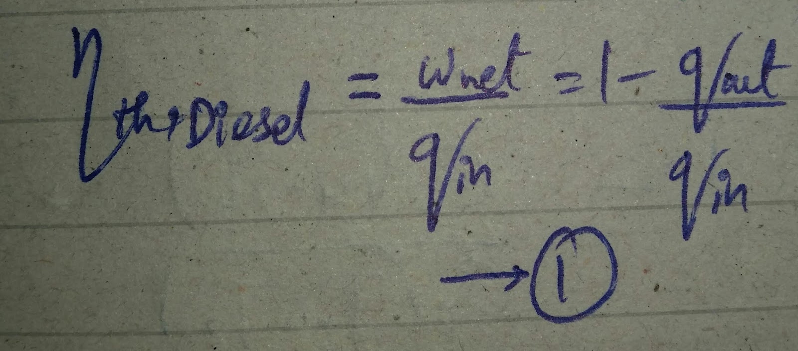
Derivation of Efficiency of Diesel Engine:
Efficiency of Diesel Engine is given by:
Note that the Diesel cycle is executed in a piston cylinder device, which forms a closed system and disregarding the kinetic and potential energy changes, the specific energy balance is given by:
Now,
For 1 ↝ 2 (Isentropic compression) and 3 ↝ 4 (Isentropic expansion)
Now, changing equation (3), we get
The derivation of Efficiency of Diesel Engine is given in the video below:
Comparison of Diesel Engine and Otto Engine:
The efficiencies of Otto and Diesel Engine is given by:
They are different by factor
Dual Cycle
It is a thermodynamic cycle that combines the Otto and Diesel cycle. In the Dual cycle, combustion occurs partly at Constant volume and partly at Constant pressure.
1 ➤ 2 : Isentropic Compression
2 ➤ 3 : Constant Volume Heat Addition
3 ➤ 4 : Constant Pressure Heat Addition
4 ➤ 5 : Isentropic Expansion
5 ➤ 1 : Constant Volume Heat Rejection
The derivation involves the following steps in the important steps are as follows:
And the derivation for dual engine cycle is given in the video below:
Types of Fuel used in Heat Engine:
There are three types of fuel commonly used which are as follows:
1. Solid Fuel:
It is used in past because of storage problem, handling, transportation, etc.
They need to be pulverized (crushed into particles/products).
They produce ash and toxic emission. For example: coal, etc.
2. Liquid Fuel:
It also have storage problem.
There is a problem of making proper air-fuel Gaseous mixture.
Liquid fuel should be highly volatile.
3. Gaseous Fuel:
They are ideal fuel and are commonly used nowadays.
They can easily male proper Gaseous air-fuel mixture.
Gases have higher volume so they also have storage problem. This exact reason why natural gas is compressed and saved as CNG (Compressed Natural Gas) in cylinders.
Note: If anyone wants me to publish a post on your topic related to mechanical engineering, Ielts, robotics, Web designing, etc, I am glad to see your interest and I can entertain you as well.
Projection: The term Projection is defined as: Presentation of an image or an object on a surface. The principles used to graphically represent 3-D objects and structures on 2-D media and it based on two variables: Line of Sight. Plane of Projection. Line of Sight & Plane of Projection: Line of sight is divided into 2 types: Parallel Projection Converging Projection & A plane of projection is an imaginary flat plane upon which the image created by the lines of sight is projected. Orthographic Projection: When the projectors are parallel to each other and perpendicular to the plane of projection. The lines pf sight of the observer create a view on the screen. The screen is referred to as the Plane of Projection (POP). The lines of sight are called Projection lines or projectors. Rules of Orthographic Projection: Edges that are parallel to a plane of projection appear as lines. Edges that are incl...
Advance High Strength Steel Conventional low carbon mild steel has simpler ferritic structure (α-iron) and good ductility. Common type of HSS is High Strength Low Alloy (HSLA) ⇥ has yield strength 550 - 690 N/sq.mm . Manganese ⇥ supporter (stabilizer) of ferrite. Conventional HSS : Is single-phase ferritic steel with a potential for some pearlite in C-Mn steel. Lower strain hardening capacity. Advance HSS : primarily steel with a microstructure containing a phase other than ferrite, pearlite, cementite. Higher strain hardening capacity. Case Study of Automobile There are three different zones in a car: Crumple Zone (Front & Back) Middle Compartment Safety Cage Some important points about these zones are: Crumple Zone ⇥ Made with those materials which absorb maximum amount of energy. Safety Cage ⇥ Multiple areas (like cabins, structural elements). Areas of Safety cage are described ahead: Cabins (Blue Areas) ⇥ Should have high streng...
Gear Forming by Machining Formation of gear through machining consists of following methods: Form Milling by Disc Cutter Form Milling by End Mill Cutter Shaper, Planner and Slotter Broaching 1. Form Milling by Disc Cutter It is defined as, " Tooth is cut one by one by plunging the rotating cutter into the blank " . Each gear needs a separate cutter. 8 - 10 standard cutters are available for producing 12 - 120 teeth gears. Used for big spur gears of large pitch. 2. Form Milling by End Mill Cutter It includes the cutting of tooth at a time and then indexed for the next tooth space for cutting. For a small volume production of low precision gears. Set of 10 cutters ↠ 12 - 120 teeth gears . Used for teeth of large gears/module. To reduce cost, same cutter is often used for multiple sized gears resulting in profile errors . Characteristics: Use of Hardened stainless steels (HSS) form milling cutters. Use of Ordinary milling machines. Low production rate (need of indexing...


You should provide dual engine efficiency derivation to better understand this topic and related topics like expansion and pressure ratio.
ReplyDelete